Nissan Qashqai J11. Manual — part 68

CYLINDER HEAD
EM-211
< UNIT DISASSEMBLY AND ASSEMBLY >
[MR20DD]
C
D
E
F
G
H
I
J
K
L
M
A
EM
N
P
O
3.
Remove valve collet.
• Compress valve spring with the valve spring compressor [SST:
KV10116200] (A), the attachment [SST: KV10115900] (C), and
the adapter [SST: KV10109220] (B). Remove valve collet with
a magnet hand.
CAUTION:
• Be careful not to damage valve lifter holes.
• Fit the attachment [SST: KV10115900 (J-26336-20)]
in
thecenter of valve spring retainer
to press it.
4.
Remove valve spring retainer and valve spring (with valve spring seat).
CAUTION:
Never remove valve spring seat from valve spring.
5.
Push valve stem to combustion chamber side, and remove valve.
• Identify installation positions, and store them without mixing them up.
6.
Remove valve oil seal with a valve oil seal puller [SST:
KV10107902] .
7.
When valve seat must be replaced.
• Bore out old seat until it collapses. Boring should not continue beyond the bottom face of the seat
recess in cylinder head. Set the machine depth stop to ensure this. Refer to
.
CAUTION:
Never bore excessively to prevent cylinder head from scratching.
8.
When valve guide must be replaced.
JPBIA0180ZZ
JPBIA4477ZZ
PBIC3210J

EM-212
< UNIT DISASSEMBLY AND ASSEMBLY >
[MR20DD]
CYLINDER HEAD
a.
To remove valve guide, heat cylinder head to 110 to 130
°
C (230
to 266
°
F) by soaking in heated oil
.
b.
Drive out valve guide with a hammer and valve guide drift (com-
mercial service tool) (A).
CAUTION:
Cylinder head contains heat, wear protective equipment to
avoid getting burned.
ASSEMBLY
1.
When valve guide is removed, install it.
CAUTION:
Replace with oversize [0.2 mm (0.008 in)] valve guide.
a.
Ream cylinder head valve guide hole with a valve guide reamer
(commercial service tool) (A).
b.
Heat cylinder head to 110 to 130
°
C (230 to 266
°
F) by soaking in
heated oil
.
PBIC3214J
JSBIA2470ZZ
For service parts: Oversize [0.2 mm (0.008 in)]
.
JPBIA0185ZZ
PBIC3214J

CYLINDER HEAD
EM-213
< UNIT DISASSEMBLY AND ASSEMBLY >
[MR20DD]
C
D
E
F
G
H
I
J
K
L
M
A
EM
N
P
O
c.
Press valve guide
from camshaft side to dimensions as
shown in the figure.
CAUTION:
Cylinder head contains heat, wear protective equipment to
avoid getting burned.
d.
Apply reamer finish to valve guide with a valve guide reamer
(commercial service tool) (A).
2.
When valve seat is removed, install it.
CAUTION:
Replace with oversize [0.5 mm (0.020 in)] valve seat.
a.
Ream cylinder head
recess diameter for service valve seat
.
• Be sure to ream in circles concentric to the valve guide center.
This will enable valve seat to fit correctly.
b.
Heat cylinder head to 110 to 130
°
C (230 to 266
°
F) by soaking in
heated oil
.
c.
Provide valve seats cooled well with dry ice. Press-fit valve seat into cylinder head.
CAUTION:
• Never touch cold valve seats directly.
• Cylinder head contains heat, wear protective equipment to avoid getting burned.
: Cylinder head
Projection (H)
: Refer to
.
PBIC3217J
Standard
: Refer to
.
JPBIA0185ZZ
For service parts: Oversize [0.5 mm (0.020 in)]
PBIC3218J
PBIC3214J
EM-214
< UNIT DISASSEMBLY AND ASSEMBLY >
[MR20DD]
CYLINDER HEAD
d.
Using valve seat cutter set (commercial service tool) (A) or valve
seat grinder, finish valve seat to the specified dimensions. For
dimensions, refer to
CAUTION:
When using valve seat cutter, firmly grip the cutter handle
with both hands. Then, press on the contacting surface all
around the circumference to cut in a single drive. Improper
pressure on with the cutter or cutting many different times
may result in stage valve seat.
e.
Using compound, grind to adjust valve fitting.
f.
Check again for normal contact. Refer to
.
3.
Install valve oil seal.
• Install with a valve oil seal drift [SST: KV10115600]
to match
dimension in the figure.
NOTE:
Dimension is height that measured before installing valve
spring (with valve spring seat).
4.
Install valve.
• Install larger diameter to intake side.
5.
Install valve spring (with valve spring seat).
• Install smaller pitch (valve spring seat side) to cylinder head
side .
• Confirm identification color
of valve spring.
6.
Install valve spring retainer.
7.
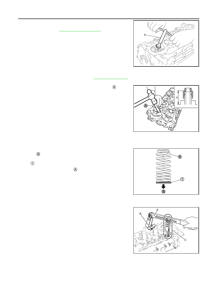
Install valve collet.
• Compress valve spring with the valve spring compressor [SST:
KV10116200] (A), the attachment [SST: KV10115900] (C), and
the adapter [SST: KV10109220] (B). Install valve collet with a
magnet hand.
CAUTION:
• Be careful not to damage valve lifter holes.
JSBIA2471ZZ
Height (H)
: 15.1 - 15.7 mm (0.594 - 0.618 in)
PBIC3211J
: Valve spring seat (Do not remove from valve spring.)
Intake
: White
Exhaust
: Orange
JPBIA4479ZZ
JPBIA0180ZZ
Нет комментариевНе стесняйтесь поделиться с нами вашим ценным мнением.
Текст