Nissan Qashqai J11. Manual — part 1149

HAC-232
< REMOVAL AND INSTALLATION >
[MANUAL AIR CONDITIONING]
DOOR MOTOR
DOOR MOTOR
Exploded View
INFOID:0000000010432592
LEFT SIDE
RIGHT SIDE
A/C unit assembly
Intake door lever
Intake door link
Intake door motor
Air mix door motor LH
JMIIA3368GB

DOOR MOTOR
HAC-233
< REMOVAL AND INSTALLATION >
[MANUAL AIR CONDITIONING]
C
D
E
F
G
H
J
K
L
M
A
B
HAC
N
O
P
AIR MIX DOOR MOTOR
AIR MIX DOOR MOTOR : Removal and Installation
INFOID:0000000010432593
REMOVAL
Air Mix Door Motor LH
1.
Set the temperature at 18
°
C (64
°
F).
CAUTION:
Always perform the above procedure when removing air mix door motor. Otherwise, air mix door
may interfere in A/C unit assembly may be damaged.
2.
Remove instrument lower panel LH (LHD models) or glove box cover (RHD models). Refer to
3.
Remove foot duct LH. Refer to
VTL-14, "FOOT DUCT : Removal and Installation"
.
4.
Disconnect air mix door motor harness connector.
5.
Remove fixing screws
, and then remove air mix door motor
LH.
A/C unit assembly
Side ventilator door lever
Foot door link
Foot door link
Main link
Mode door link
Mode door motor
JMIIA3531ZZ
JMIIA3395ZZ

HAC-234
< REMOVAL AND INSTALLATION >
[MANUAL AIR CONDITIONING]
DOOR MOTOR
INSTALLATION
Note the following item, and then install in the reverse order of removal.
CAUTION:
After installing door motor, perform door motor starting position. Refer to
INTAKE DOOR MOTOR
INTAKE DOOR MOTOR : Removal and Installation
INFOID:0000000010432594
REMOVAL
1.
Remove instrument lower panel LH (LHD models) or glove box cover (RHD models). Refer to
2.
Disconnect intake door motor harness connector.
3.
Remove fixing screws
, and then remove intake door motor.
INSTALLATION
Install in the reverse order of removal.
MODE DOOR MOTOR
MODE DOOR MOTOR : Removal and Installation
INFOID:0000000010432595
REMOVAL
1.
Remove instrument lower panel RH (RHD models) or glove box cover (LHD models). Refer to
2.
Remove foot duct RH. Refer to
VTL-14, "FOOT DUCT : Removal and Installation"
3.
Disconnect mode door motor harness connector.
4.
Remove fixing screws
, mode door motor.
INSTALLATION
Note the following item, and then install in the reverse order of removal.
CAUTION:
After installing door motor, perform door motor starting position. Refer to
JMIIA3394ZZ
JMIIA3396ZZ
PRECAUTIONS
HAC-235
< PRECAUTION >
[MANUAL HEATER ]
C
D
E
F
G
H
J
K
L
M
A
B
HAC
N
O
P
PRECAUTION
PRECAUTIONS
Precaution for Supplemental Restraint System (SRS) "AIR BAG" and "SEAT BELT
PRE-TENSIONER"
INFOID:0000000010433386
The Supplemental Restraint System such as “AIR BAG” and “SEAT BELT PRE-TENSIONER”, used along
with a front seat belt, helps to reduce the risk or severity of injury to the driver and front passenger for certain
types of collision. Information necessary to service the system safely is included in the “SRS AIR BAG” and
“SEAT BELT” of this Service Manual.
WARNING:
Always observe the following items for preventing accidental activation.
• To avoid rendering the SRS inoperative, which could increase the risk of personal injury or death in
the event of a collision that would result in air bag inflation, all maintenance must be performed by
an authorized NISSAN/INFINITI dealer.
• Improper maintenance, including incorrect removal and installation of the SRS, can lead to personal
injury caused by unintentional activation of the system. For removal of Spiral Cable and Air Bag
Module, see “SRS AIR BAG”.
• Never use electrical test equipment on any circuit related to the SRS unless instructed to in this Ser-
vice Manual. SRS wiring harnesses can be identified by yellow and/or orange harnesses or harness
connectors.
PRECAUTIONS WHEN USING POWER TOOLS (AIR OR ELECTRIC) AND HAMMERS
WARNING:
Always observe the following items for preventing accidental activation.
• When working near the Air Bag Diagnosis Sensor Unit or other Air Bag System sensors with the
ignition ON or engine running, never use air or electric power tools or strike near the sensor(s) with
a hammer. Heavy vibration could activate the sensor(s) and deploy the air bag(s), possibly causing
serious injury.
• When using air or electric power tools or hammers, always switch the ignition OFF, disconnect the
battery, and wait at least 3 minutes before performing any service.
Precautions for Removing Battery Terminal
INFOID:0000000010521164
• With the adoption of Auto ACC function, ACC power is automatically supplied by operating the intelligent key
or remote keyless entry or by opening/closing the driver side door. In addition, ACC power is supplied even
after the ignition switch is turned to the OFF position, i.e. ACC power is supplied for a certain fixed time.
• When disconnecting the 12V battery terminal, turn off the ACC
power before disconnecting the 12V battery terminal, observing
“How to disconnect 12V battery terminal” described below.
NOTE:
Some ECUs operate for a certain fixed time even after ignition
switch is turned OFF and ignition power supply is stopped. If the
battery terminal is disconnected before ECU stops, accidental DTC
detection or ECU data damage may occur.
• For vehicles with the 2-batteries, be sure to connect the main bat-
tery and the sub battery before turning ON the ignition switch.
NOTE:
If the ignition switch is turned ON with any one of the terminals of
main battery and sub battery disconnected, then DTC may be detected.
• After installing the 12V battery, always check "Self Diagnosis Result" of all ECUs and erase DTC.
NOTE:
The removal of 12V battery may cause a DTC detection error.
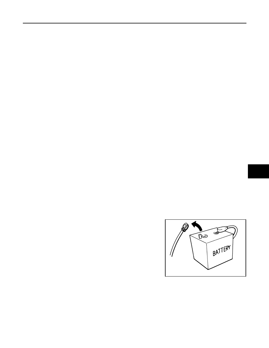
HOW TO DISCONNECT 12V BATTERY TERMINAL
Disconnect 12V battery terminal according to instruction described below.
1.
Open the hood.
2.
Turn ignition switch to the ON position.
3.
Turn ignition switch to the OFF position with the driver side door opened.
4.
Get out of the vehicle and close the driver side door.
SEF289H
Нет комментариевНе стесняйтесь поделиться с нами вашим ценным мнением.
Текст