Nissan Qashqai J11. Manual — part 1042
VTL-14
< REMOVAL AND INSTALLATION >
DUCT AND GRILLE
2.
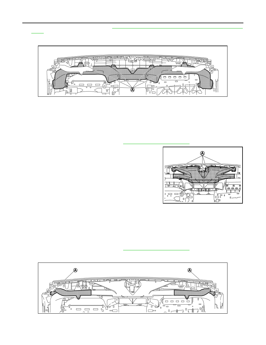
Remove front defroster nozzle. Refer to
VTL-14, "CENTER DEFROSTER NOZZLE : Removal and Instal-
.
3.
Remove fixing screws (A), and then remove center ventilator duct assembly from instrument panel
assembly.
INSTALLATION
Install in the reverse order of removal.
CENTER DEFROSTER NOZZLE
CENTER DEFROSTER NOZZLE : Removal and Installation
INFOID:0000000010451818
REMOVAL
1.
Remove instrument panel assembly. Refer to
IP-13, "Removal and Installation"
.
2.
Remove fixing screws (A), and then remove center defroster
nozzle from instrument panel assembly.
INSTALLATION
Install in the reverse order of removal.
SIDE DEFROSTER NOZZLE
SIDE DEFROSTER NOZZLE : Removal and Installation
INFOID:0000000010451819
REMOVAL
1.
Remove instrument panel assembly. Refer to
IP-13, "Removal and Installation"
.
2.
Remove fixing screws (A), and then remove side defroster nozzle LH and RH from instrument panel
assembly.
INSTALLATION
Install in the reverse order of removal.
JMIIA3410ZZ
JMIIA3380ZZ
JMIIA3381ZZ
DUCT AND GRILLE
VTL-15
< REMOVAL AND INSTALLATION >
C
D
E
F
G
H
J
K
L
M
A
B
VTL
N
O
P
SIDE DEFROSTER GRILLE
SIDE DEFROSTER GRILLE : Removal and Installation
INFOID:0000000010451820
REMOVAL
1.
Remove side defroster nozzle. Refer to
VTL-14, "SIDE DEFROSTER NOZZLE : Removal and Installa-
2.
Disengage fixing pawl, and then remove side defroster grille LH or RH.
INSTALLATION
Install in the reverse order of removal.
FOOT DUCT
FOOT DUCT : Removal and Installation
INFOID:0000000010451821
REMOVAL
Foot Duct LH
1.
Remove instrument lower cover. Refer to
IP-13, "Removal and Installation"
. (LHD models)
2.
Remove glove box cover. Refer to
IP-13, "Removal and Installation"
3.
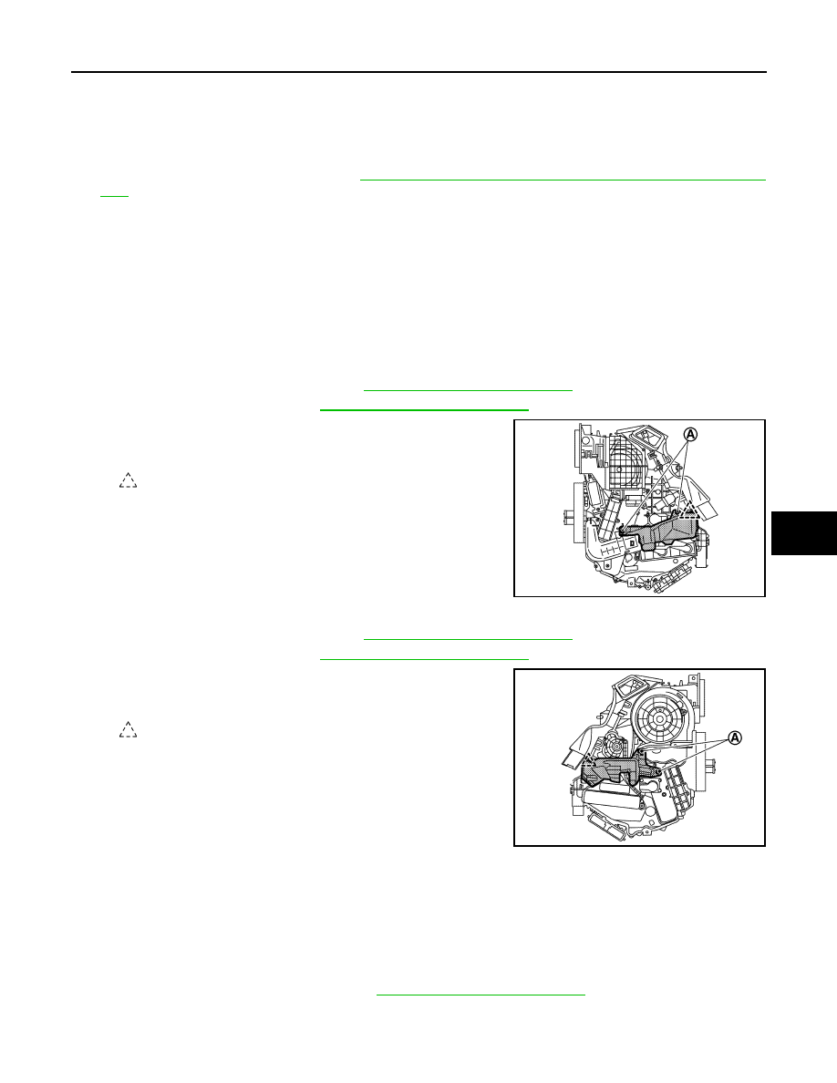
Remove fixing screws (A) and pawl, and then remove foot duct
LH.
Foot Duct RH
1.
Remove instrument lower cover. Refer to
IP-13, "Removal and Installation"
. (RHD models)
2.
Remove glove box cover. Refer to
IP-13, "Removal and Installation"
3.
Remove fixing screws (A) and pawl, and then remove foot duct
RH.
INSTALLATION
Install in the reverse order of removal.
REAR FLOOR DUCT 1
REAR FLOOR DUCT 1 : Removal and Installation
INFOID:0000000010451822
REMOVAL
1.
Remove center console assembly. Refer to
IP-19, "Removal and Installation"
.
2.
Disengage fixing pawls, and then remove rear floor duct 1.
INSTALLATION
: Pawl
JMIIA3371ZZ
: Pawl
JMIIA3370ZZ
VTL-16
< REMOVAL AND INSTALLATION >
DUCT AND GRILLE
Install in the reverse order of removal.
REAR FLOOR DUCT 2
REAR FLOOR DUCT 2 : Removal and Installation
INFOID:0000000010451874
REMOVAL
1.
Remove front seat assembly. Refer to
SE-29, "Removal and Installation"
2.
Remove dush side finisher and center pillar lower garnish. Refer to
INT-18, "Removal and Installation"
.
3.
Remove center console assembly. Refer to
IP-19, "Removal and Installation"
4.
Peel off floor carpet of front side. Refer to
INT-22, "Removal and Installation"
5.
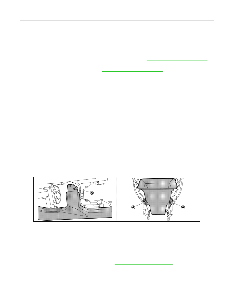
Disconnect fixing clips and harness clip, and then remove rear floor duct 2 LH or RH.
INSTALLATION
Install in the reverse order of removal.
REAR VENTILATOR DUCT 1
REAR VENTILATOR DUCT 1 : Removal and Installation
INFOID:0000000010787480
REMOVAL
1.
Remove instrument panel assembly. Refer to
IP-13, "Removal and Installation"
.
2.
Disengage pawls, and then remove rear ventilator duct 1.
INSTALLATION
Install in the reverse order of removal.
REAR VENTILATOR DUCT 2
REAR VENTILATOR DUCT 2 : Removal and Installation
INFOID:0000000010787481
REMOVAL
1.
Remove center console assembly. Refer to
IP-19, "Removal and Installation"
2.
Remove fixing screws (A), and then remove rear ventilator duct 2 .
INSTALLATION
Install in the reverse order of removal.
REAR VENTILATOR GRILLE
REAR VENTILATOR GRILLE : Removal and Installation
INFOID:0000000010787482
REMOVAL
1.
Remove console rear finisher assembly. Refer to
IP-19, "Removal and Installation"
JMIIA3340ZZ
BLOWER MOTOR
VTL-17
< REMOVAL AND INSTALLATION >
C
D
E
F
G
H
J
K
L
M
A
B
VTL
N
O
P
BLOWER MOTOR
Exploded View
INFOID:0000000010451823
Refer to
Removal and Installation
INFOID:0000000010451824
REMOVAL
1.
Remove instrument panel assembly. Refer to
IP-13, "Removal and Installation"
.
2.
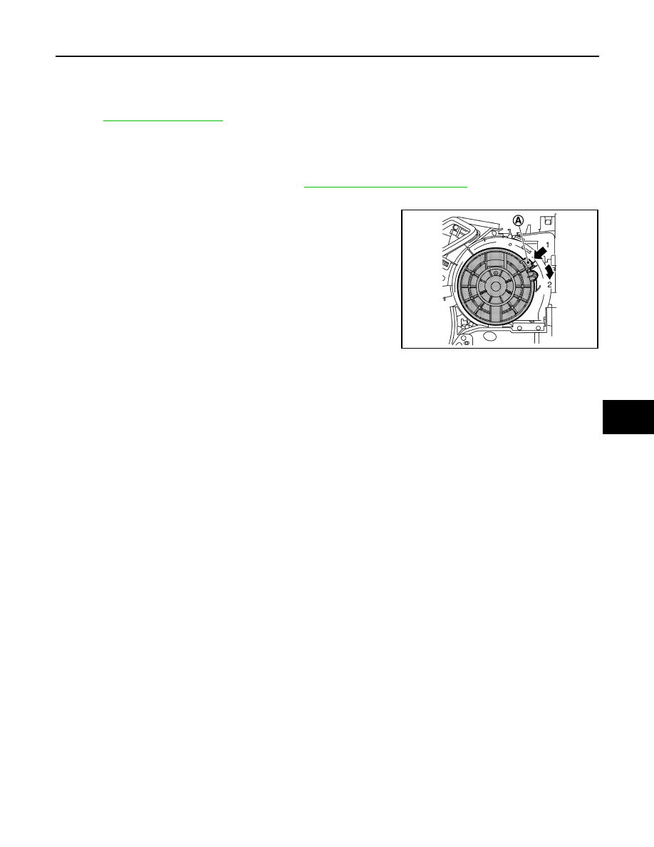
Disconnect blower motor connector and remove fixing screw.
3.
Press flange holding hook (A), and then turn blower motor clock-
wise according numerical order 1
→
2 indicated by arrows as
shown in the figure.
4.
Pull outside, and then remove blower motor.
INSTALLATION
Install in the reverse order of removal.
JMIIA3373ZZ
Нет комментариевНе стесняйтесь поделиться с нами вашим ценным мнением.
Текст