Nissan Versa Note. Manual — part 485
HA-10
< PREPARATION >
PREPARATION
Sealant and/or Oil
INFOID:0000000009457537
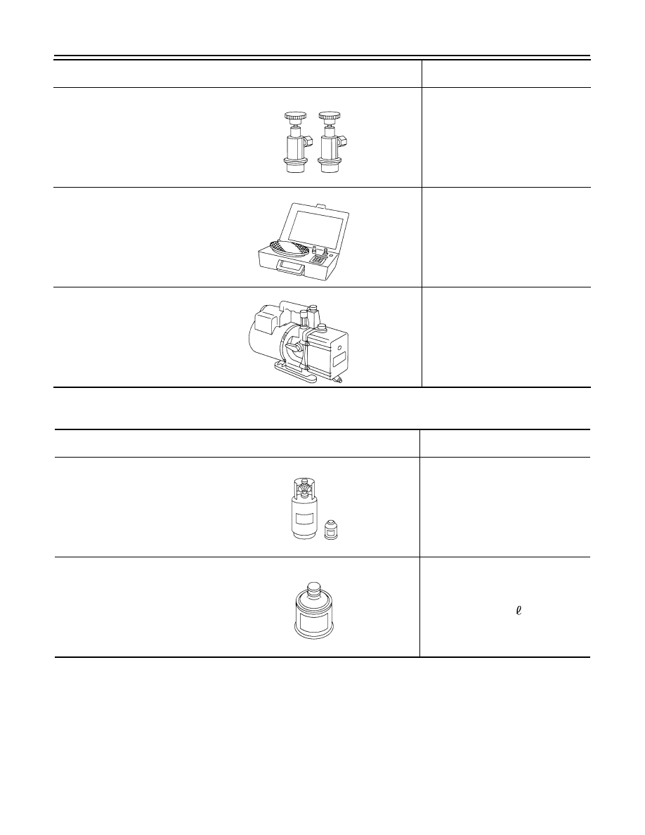
Service couplers
• High side coupler
(J-39500-20A)
• Low side coupler
(J-39500-24A)
Hose fitting to service hose:
• M14 x 1.5 fitting is optional or per-
manently attached.
(J-39699)
Refrigerant weight scale
For measuring of refrigerant
Fitting size-Thread size
• 1/2”-16 ACME
(J-39649)
Vacuum pump
(Including the isolator valve)
Capacity:
• Air displacement: 4 CFM
• Micron rating: 20 microns
• Oil capacity: 482 g (17 oz)
Fitting size-Thread size
• 1/2”-16 ACME
(Kent-Moore No.)
Tool name
Description
S-NT202
S-NT200
S-NT203
(Kent-Moore No.)
Tool name
Description
( — )
HFC-134a (R-134a) Refrigerant
Container color: Light blue
Container marking: HFC-134a (R-
134a)
Fitting size: Thread size
• large container 1/2”-16 ACME
( — )
NISSAN A/C System Oil Type DH-
PR
Type: Poly alkylene glycol (PAG), type
DH-PR
Application: HFC-134a (R-134a) Vane-
rotary compressors
Capacity: 110 - 130 m (3.7 - 4.4 US fl
oz, 3.9 - 4.6 Imp fl oz)
S-NT196
JMIIA1759ZZ

COMPONENT PARTS
HA-11
< SYSTEM DESCRIPTION >
C
D
E
F
G
H
J
K
L
M
A
B
HA
N
O
P
SYSTEM DESCRIPTION
COMPONENT PARTS
Component Parts Location
INFOID:0000000008968507
AWIIA1694ZZ
Component
Function
1.
Compressor
Intakes, compresses, discharges and circulates refrigerant.
2.
Condenser
Cools the high-temperature high-pressure refrigerant discharged from the compressor to
change it into a liquid.
3.
Liquid tank
Filters and stores a reserve of liquid refrigerant.
4.
Pressure sensor
Senses refrigerant pressure for proper A/C cycle operation.
5.
Evaporator
Evaporates refrigerant which removes heat from the air lowering its temperature.
6.
Expansion valve
Transforms high-pressure liquid refrigerant to low-pressure liquid refrigerant.

HA-12
< BASIC INSPECTION >
DIAGNOSIS AND REPAIR WORKFLOW
BASIC INSPECTION
DIAGNOSIS AND REPAIR WORKFLOW
Workflow
INFOID:0000000009541021
OVERALL SEQUENCE
DETAILED FLOW
1.
INTERVIEW CUSTOMER
Interview the customer to obtain as much information as possible about the conditions and environment under
which the malfunction occurred.
ALIIA0440GB

DIAGNOSIS AND REPAIR WORKFLOW
HA-13
< BASIC INSPECTION >
C
D
E
F
G
H
J
K
L
M
A
B
HA
N
O
P
>> GO TO 2.
2.
SYMPTOM CHECK
Verify symptoms.
>> GO TO 3.
3.
CHECK FOR DTCS
With CONSULT
1. Turn ignition switch ON.
2. Select “Self Diagnostic Result” mode of “BCM” using CONSULT.
3. Check DTC.
Is any DTC detected?
YES
>> GO TO 4.
NO
>> GO TO 5.
4.
PERFORM DTC DIAGNOSTIC PROCEDURE
Perform the diagnostic procedure for the detected DTC. Refer to
BCS-47, "DTC Inspection Priority Chart"
(with Intelligent Key) or
BCS-109, "DTC Inspection Priority Chart"
(without Intelligent Key).
>> GO TO 7.
5.
OPERATION CHECK
Perform the operation check. Refer to
.
>> GO TO 6.
6.
SYMPTOM DIAGNOSIS
Check the symptom diagnosis table. Refer to
.
>> GO TO 8.
7.
VERIFY REPAIR.
With CONSULT
1. Turn ignition switch ON.
2. Select “Self Diagnostic Result” mode of “BCM” using CONSULT.
3. Check DTC.
Is any DTC detected?
YES
>> GO TO 4.
NO
>> GO TO 8.
8.
PERFORM FINAL OPERATION CHECK
Perform the operation check. Refer to
.
Does it operate normally?
YES
>> Inspection End.
NO
>> GO TO 2.
Нет комментариевНе стесняйтесь поделиться с нами вашим ценным мнением.
Текст