Nissan Altima L32. Manual — part 1579

HAZARD WARNING LAMPS FLASH
WT-59
< SYMPTOM DIAGNOSIS >
C
D
F
G
H
I
J
K
L
M
A
B
WT
N
O
P
HAZARD WARNING LAMPS FLASH
Hazard Warning Lamps Flash When Ignition Switch Is Turned On
INFOID:0000000004205319
DIAGNOSTIC PROCEDURE
1.
CHECK BCM GROUND CIRCUIT
Check BCM ground circuit. Refer to
.
Is the inspection result normal?
YES
>> Replace BCM. Refer to
BCS-96, "Removal and Installation"
NO
>> Repair BCM ground circuit.
WT-60
< SYMPTOM DIAGNOSIS >
ID REGISTRATION CANNOT BE COMPLETED
ID REGISTRATION CANNOT BE COMPLETED
ID Registration Cannot Be Completed
INFOID:0000000004205320
DIAGNOSTIC PROCEDURE
1.
PERFORM ID REGISTRATION OF ALL TRANSMITTERS
Carry out ID registration of all transmitters. Refer to
WT-6, "ID Registration Procedure"
Can ID registration of all transmitters be completed?
YES
>> Inspection End.
NO
>> GO TO
NOISE, VIBRATION AND HARSHNESS (NVH) TROUBLESHOOTING
WT-61
< SYMPTOM DIAGNOSIS >
C
D
F
G
H
I
J
K
L
M
A
B
WT
N
O
P
NOISE, VIBRATION AND HARSHNESS (NVH) TROUBLESHOOTING
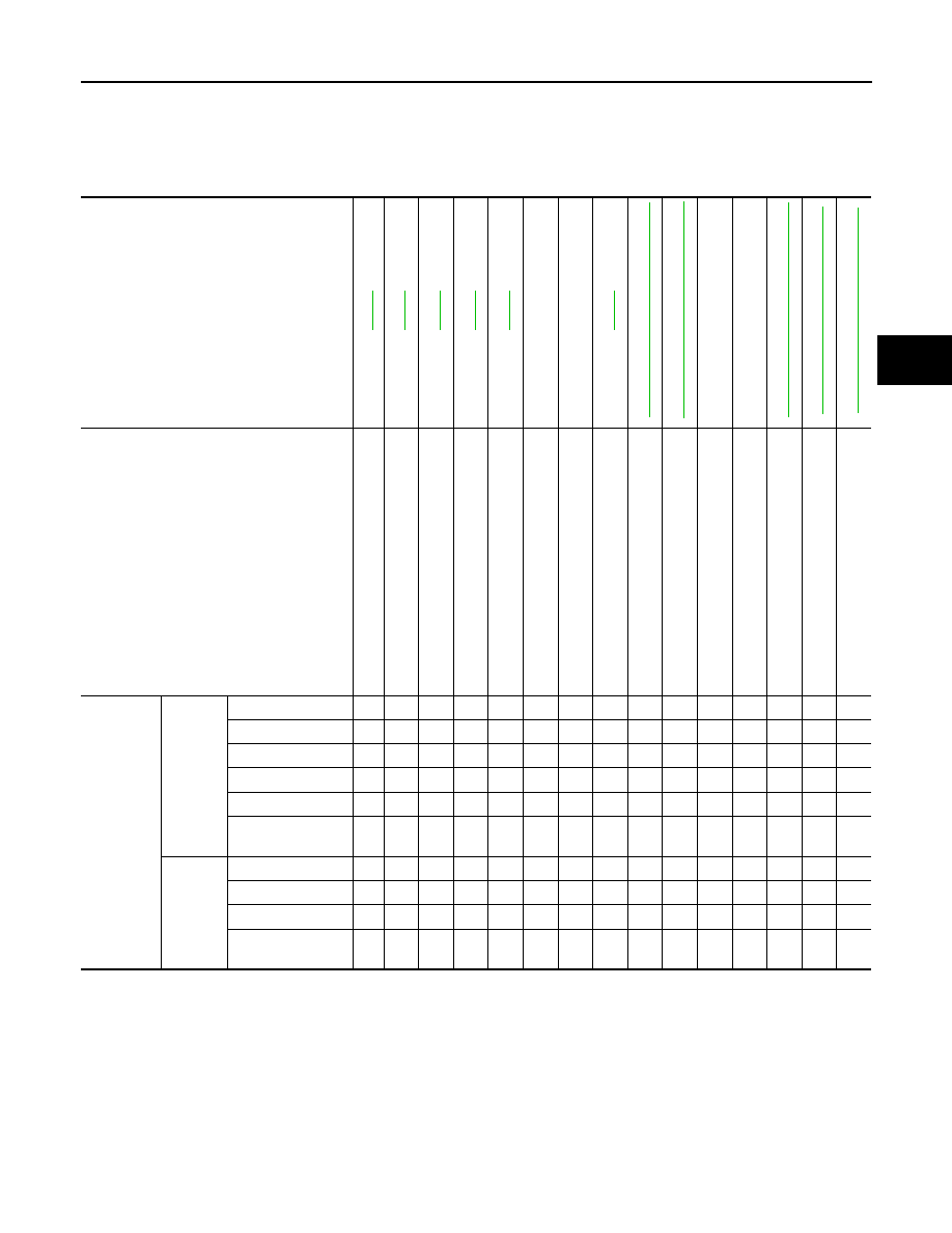
NVH Troubleshooting Chart
INFOID:0000000004205321
Use chart below to help you find the cause of the symptom. If necessary, repair or replace these parts.
×: Applicable
Reference page
—
—
Refe
r to
TI
RE
S in
th
is chart
.
Re
fer to
ROAD
W
H
EEL in thi
s ch
art.
"
"
Possible cause and SUSPECTED PARTS
Im
pr
op
er i
n
st
al
la
tio
n
, lo
os
en
es
s
O
ut
-of-ro
un
d
Im
ba
la
nc
e
Incorrect t
ire
pressure
Uneven tire
wear
Def
orm
ati
on
or
da
ma
ge
No
n-u
n
iformi
ty
In
co
rrec
t t
ire
si
ze
FRONT A
X
LE
AND FRONT SUSP
ENSION
REAR A
X
LE
AND REAR SUSP
ENSION
TI
RE
S
ROAD WHEE
LS
DRIVE SHAFT
BRAKE
STE
E
RING
Symptom
TIRES
Noise
×
×
×
×
×
×
×
×
×
×
×
×
×
Shake
×
×
×
×
×
×
×
×
×
×
×
×
×
Vibration
×
×
×
×
×
×
Shimmy
×
×
×
×
×
×
×
×
×
×
×
×
×
Shudder
×
×
×
×
×
×
×
×
×
×
×
×
Poor quality ride or
handling
×
×
×
×
×
×
×
×
×
×
ROAD
WHEEL
Noise
×
×
×
×
×
×
×
×
×
×
Shake
×
×
×
×
×
×
×
×
×
×
Shimmy, Shudder
×
×
×
×
×
×
×
×
×
Poor quality ride or
handling
×
×
×
×
×
×
×
WT-62
< PRECAUTION >
PRECAUTIONS
PRECAUTION
PRECAUTIONS
Supplemental Restraint System (SRS) AIR BAG and SEAT BELT PRE-TEN-
SIONER
INFOID:0000000004205322
The Supplemental Restraint System such as “AIR BAG” and “SEAT BELT PRE-TENSIONER”, used along
with a front seat belt, helps to reduce the risk or severity of injury to the driver and front passenger for certain
types of collision. This system includes seat belt switch inputs and dual stage front air bag modules. The SRS
system uses the seat belt switches to determine the front air bag deployment, and may only deploy one front
air bag, depending on the severity of a collision and whether the front occupants are belted or unbelted.
Information necessary to service the system safely is included in the SR and SB section of this Service Man-
ual.
WARNING:
• To avoid rendering the SRS inoperative, which could increase the risk of personal injury or death in
the event of a collision which would result in air bag inflation, all maintenance must be performed by
an authorized NISSAN/INFINITI dealer.
• Improper maintenance, including incorrect removal and installation of the SRS, can lead to personal
injury caused by unintentional activation of the system. For removal of Spiral Cable and Air Bag
Module, see the SR section.
• Do not use electrical test equipment on any circuit related to the SRS unless instructed to in this
Service Manual. SRS wiring harnesses can be identified by yellow and/or orange harnesses or har-
ness connectors.
Necessary for Steering Wheel Rotation After Battery Disconnect
INFOID:0000000004501330
NOTE:
• Before removing and installing any control units, first turn the push-button ignition switch to the LOCK posi-
tion, then disconnect both battery cables.
• After finishing work, confirm that all control unit connectors are connected properly, then re-connect both
battery cables.
• Always use CONSULT-III to perform self-diagnosis as a part of each function inspection after finishing work.
If a DTC is detected, perform trouble diagnosis according to self-diagnosis results.
This vehicle is equipped with a push-button ignition switch and a steering lock unit.
If the battery is disconnected or discharged, the steering wheel will lock and cannot be turned.
If turning the steering wheel is required with the battery disconnected or discharged, follow the procedure
below before starting the repair operation.
OPERATION PROCEDURE
1. Connect both battery cables.
NOTE:
Supply power using jumper cables if battery is discharged.
2. Carry the Intelligent Key or insert it to the key slot and turn the push-button ignition switch to ACC position.
(At this time, the steering lock will be released.)
3. Disconnect both battery cables. The steering lock will remain released with both battery cables discon-
nected and the steering wheel can be turned.
4. Perform the necessary repair operation.
5. When the repair work is completed, re-connect both battery cables. With the brake pedal released, turn
the push-button ignition switch from ACC position to ON position, then to LOCK position. (The steering
wheel will lock when the push-button ignition switch is turned to LOCK position.)
6. Perform self-diagnosis check of all control units using CONSULT-III.
Precaution for work
INFOID:0000000004205323
• After removing and installing the opening/closing parts, be sure to carry out fitting adjustments to check their
operation.
• Check the lubrication level, damage, and wear of each part. If necessary, grease or replace it.
Нет комментариевНе стесняйтесь поделиться с нами вашим ценным мнением.
Текст