Nissan Pathfinder (2008 year). Manual — part 580

STR-1
ENGINE
C
D
E
F
G
H
I
J
K
L
M
SECTION
STR
A
STR
N
O
P
CONTENTS
STARTING SYSTEM
PRECAUTION . . . . . . . . . . . ...
PRECAUTIONS . . . . . . . . . . . . ...
Precaution for Power Generation Variable Voltage
Control System . . . . . . . . . . . . . . ..
PREPARATION . . . . . . . . . . .
PREPARATION . . . . . . . . . . . . ...
Special Service Tool . . . . . . . . . . . .....
Commercial Service Tool . . . . . . . . . . ..
BASIC INSPECTION . . . . . . . . .
DIAGNOSIS AND REPAIR WORKFLOW . . ..
Work Flow . . . . . . . . . . . . . . . .....
FUNCTION DIAGNOSIS . . . . . . . ...
STARTING SYSTEM . . . . . . . . . . ...
System Diagram . . . . . . . . . . . . . ....
System Description . . . . . . . . . . . . ...
Component Parts Location . . . . . . . . . ....
Component Description . . . . . . . . . . ....
COMPONENT DIAGNOSIS . . . . . . ..
B TERMINAL CIRCUIT . . . . . . . . . ..
Description . . . . . . . . . . . . . . . ....
Diagnosis Procedure . . . . . . . . . . . ....
S CONNECTOR CIRCUIT . . . . . . . . .
Description . . . . . . . . . . . . . . . ...
Diagnosis Procedure . . . . . . . . . . . ...
STARTING SYSTEM . . . . . . . . . . .
Wiring Diagram . . . . . . . . . . . . . .
SYMPTOM DIAGNOSIS . . . . . . . ..
STARTING SYSTEM . . . . . . . . . . .
Symptom Table . . . . . . . . . . . . . ...
ON-VEHICLE REPAIR . . . . . . . . .
STARTER MOTOR . . . . . . . . . . ...
Removal and Installation . . . . . . . . . . .
SERVICE DATA AND SPECIFICATIONS
(SDS) . . . . . . . . . . . . . . .
STARTER MOTOR . . . . . . . . . . ...

STR-2
< PRECAUTION >
PRECAUTIONS
PRECAUTION
PRECAUTIONS
Precaution for Supplemental Restraint System (SRS) "AIR BAG" and "SEAT BELT
PRE-TENSIONER"
INFOID:0000000001281952
The Supplemental Restraint System such as “AIR BAG” and “SEAT BELT PRE-TENSIONER”, used along
with a front seat belt, helps to reduce the risk or severity of injury to the driver and front passenger for certain
types of collision. This system includes seat belt switch inputs and dual stage front air bag modules. The SRS
system uses the seat belt switches to determine the front air bag deployment, and may only deploy one front
air bag, depending on the severity of a collision and whether the front occupants are belted or unbelted.
Information necessary to service the system safely is included in the SR and SB section of this Service Man-
ual.
WARNING:
• To avoid rendering the SRS inoperative, which could increase the risk of personal injury or death in
the event of a collision which would result in air bag inflation, all maintenance must be performed by
an authorized NISSAN/INFINITI dealer.
• Improper maintenance, including incorrect removal and installation of the SRS, can lead to personal
injury caused by unintentional activation of the system. For removal of Spiral Cable and Air Bag
Module, see the SR section.
• Do not use electrical test equipment on any circuit related to the SRS unless instructed to in this
Service Manual. SRS wiring harnesses can be identified by yellow and/or orange harnesses or har-
ness connectors.
Precaution for Power Generation Variable Voltage Control System
INFOID:0000000001303477
CAUTION:
For this model, the battery current sensor that is installed to the negative battery cable measures the
charging/discharging current of the battery and performs various engine controls. If an electrical com-
ponent is connected directly to the negative battery terminal, the current flowing through that compo-
nent will not be measured by the battery current sensor. This condition may cause a malfunction of
the engine control system and battery discharge may occur. Do not connect an electrical component
or ground wire directly to the battery terminal.

PREPARATION
STR-3
< PREPARATION >
C
D
E
F
G
H
I
J
K
L
M
A
STR
N
P
O
PREPARATION
PREPARATION
Special Service Tool
INFOID:0000000001281953
Commercial Service Tool
INFOID:0000000001281954
Tool number
(Kent Moore No.)
Tool name
Description
—
(J-48087)
Battery Service Center
Tests Battery.
For operating instructions, refer to Technical
Service Bulletin and Battery Service Center
User Guide.
—
(J-44373) Model 620
Starting/Charging system tester
Tests starting and charging systems.
For operating instructions, refer to Technical
Service Bulletin.
WKIA5280E
SEL403X
Tool name
Description
Power tool
Loosening bolts and nuts
PBIC0190E

STR-4
< BASIC INSPECTION >
DIAGNOSIS AND REPAIR WORKFLOW
BASIC INSPECTION
DIAGNOSIS AND REPAIR WORKFLOW
Work Flow
INFOID:0000000001714428
OVERALL SEQUENCE
DETAILED FLOW
ALBIA0417GB

DIAGNOSIS AND REPAIR WORKFLOW
STR-5
< BASIC INSPECTION >
C
D
E
F
G
H
I
J
K
L
M
A
STR
N
P
O
NOTE:
To ensure a complete and thorough diagnosis, the battery, starter motor and alternator test segments must be
done as a set from start to finish.
1.
DIAGNOSIS WITH STARTING/CHARGING SYSTEM TESTER
Perform the starting system test with Starting/Charging System Tester (J-44373). For details and operating
instructions, refer to Technical Service Bulletin.
Test result
CRANKING VOLTAGE NORMAL>>GO TO 2
CRANKING VOLTAGE LOW>>GO TO 5
CHARGE BATTERY>>Perform the slow battery charging procedure. (Initial rate of charge is 10A for 12
hours.) Perform battery test again. Refer to Technical Service Bulletin.
REPLACE BATTERY>>Before replacing battery, clean the battery cable clamps and battery posts. Perform
battery test again. Refer to Technical Service Bulletin. If second test result is “REPLACE BAT-
TERY”, then do so. Perform battery test again to confirm repair.
2.
CRANKING CHECK
Check that the starter motor operates properly.
Does the engine crank normally?
YES
>> GO TO 3
NO
>> GO TO 4
3.
ENGINE START CHECK
Check that the engine starts.
Does the engine start?
YES
>> Starter motor is OK. Inspection end.
NO
>> Perform further diagnosis of engine mechanical or engine control system. Refer to EM and EC
sections. Once resolved, perform battery test again.
4.
STARTER MOTOR ACTIVATION
Check that the starter motor operates.
Does the starter motor turn?
YES
>> Check ring gear and starter motor drive pinion. Once resolved, perform battery test again.
NO
>> GO TO 7
5.
COMPARISON BETWEEN ENGINE COOLANT AND CRANKING VOLTAGE
Compare the engine coolant temperature and verify the cranking voltage is within specification.
Minimum Specification of Cranking Voltage Referencing Coolant Temperature
Is the voltage less than the specified value?
YES
>> GO TO 7
NO
>> GO TO 6
6.
STARTER OPERATION
Check the starter operation.
Does the starter motor turn smoothly?
YES
>> Starter motor is OK. Inspection end.
NO
>> GO TO 7
7.
“B” TERMINAL CIRCUIT INSPECTION
Check “B” terminal circuit. Refer to
.
Is “B” terminal circuit normal?
Engine coolant temperature [
°
C (
°
F)]
Voltage [V]
−
30 to
−
20 (
−
22 to
−
4)
8.6
−
19 to
−
10 (
−
2 to 14)
9.1
−
9 to 0 (16 to 32)
9.5
More than 1 (More than 34)
9.9

STR-6
< BASIC INSPECTION >
DIAGNOSIS AND REPAIR WORKFLOW
YES
>> GO TO 8
NO
>> Repair as needed.
8.
“S” CONNECTOR CIRCUIT INSPECTION
Check “S” connector circuit. Refer to
.
Is “S” connector circuit normal?
YES
>> GO TO 9
NO
>> Repair as needed.
9.
ENGINE ROTATION STATUS
Check that the engine can be rotated by hand.
Does the engine turn freely by hand?
YES
>> Replace starter motor.
NO
>> Perform further diagnosis of engine mechanical or powertrain mechanism. Refer to EM or TM
sections. Once resolved, perform battery test again. Refer to Technical Service Bulletin.
STARTING SYSTEM
STR-7
< FUNCTION DIAGNOSIS >
C
D
E
F
G
H
I
J
K
L
M
A
STR
N
P
O
FUNCTION DIAGNOSIS
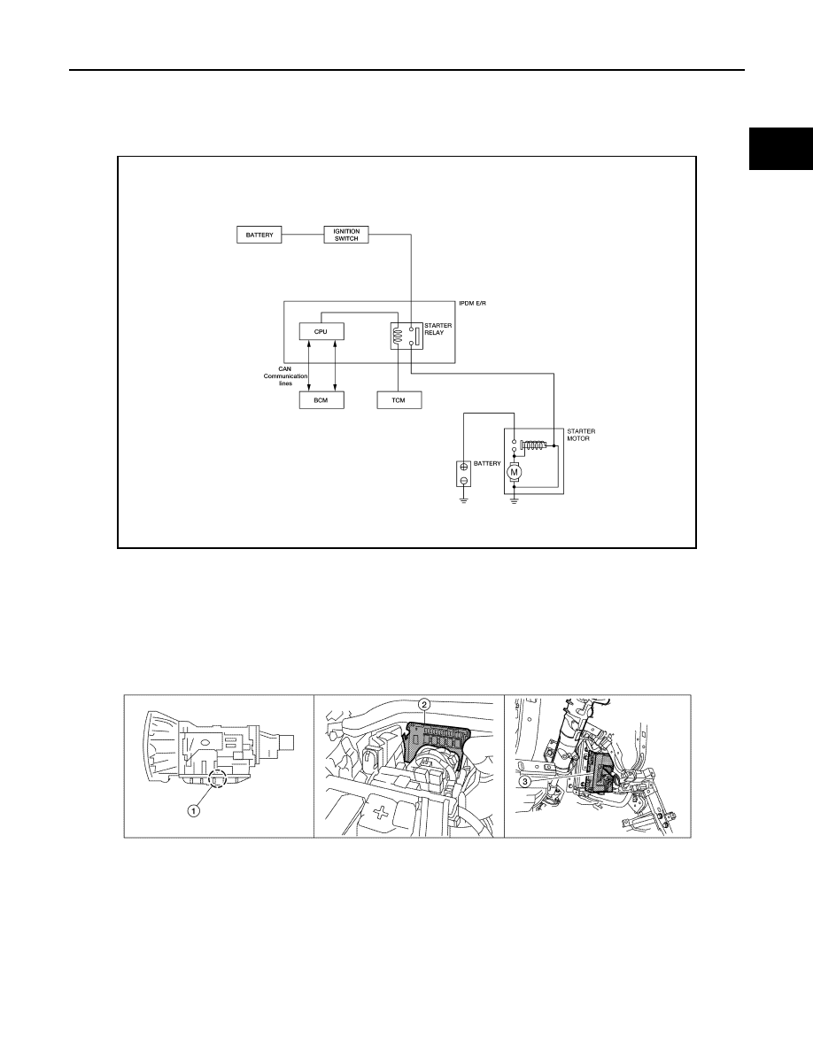
STARTING SYSTEM
System Diagram
INFOID:0000000001714429
System Description
INFOID:0000000001714430
The starter motor plunger closes and provides a closed circuit between the battery and the starter motor. The
starter motor is grounded to the cylinder block. With power and ground supplied, the starter motor operates.
Component Parts Location
INFOID:0000000001714431
ALBIA0416GB
1.
A/T assembly F9 (with built in TCM
F502)
2.
IPDM E/R E119, E120, E122, E124
3.
BCM M18 (view with instrument panel
lower LH panel removed)
AWBIA0127ZZ

STR-8
< FUNCTION DIAGNOSIS >
STARTING SYSTEM
Component Description
INFOID:0000000001714432
Component part
Description
TCM
TCM supplies power to the starter relay inside the IPDM E/R
when the selector lever is shifted to the P or N position.
BCM
BCM sends a starter request signal to the CPU of the IPDM E/R
over the CAN communication lines.
IPDM E/R
CPU inside IPDM E/R operates the starter relay at the request of
the BCM over the CAN communication lines.
Starter motor
The starter motor plunger closes and the motor is supplied with
battery power, which in turn cranks the engine, when the “S” ter-
minal is supplied with electric power.
Нет комментариевНе стесняйтесь поделиться с нами вашим ценным мнением.
Текст