Nissan Pathfinder (2008 year). Manual — part 483

LU-26
< ON-VEHICLE MAINTENANCE >
[VK56DE]
ENGINE OIL
8.
Check the oil level using the dipstick as shown. Add oil as nec-
essary and install the oil filler cap. Refer to
.
CAUTION:
Do not overfill the engine with oil.
SMA954C

OIL FILTER
LU-27
< ON-VEHICLE MAINTENANCE >
[VK56DE]
C
D
E
F
G
H
I
J
K
L
M
A
LU
N
P
O
OIL FILTER
Removal and Installation
INFOID:0000000001297366
REMOVAL
1.
Remove the engine front undercover access plate using power tool.
2.
Remove the oil filter using Tool as shown.
WARNING:
Be careful not to burn yourself, as the engine and engine oil
may be hot.
CAUTION:
• The oil filter is equipped with a pressure relief valve.
• Use Genuine NISSAN oil filter or equivalent.
• When removing, prepare a shop cloth to absorb any
engine oil leaks or spills.
• Do not allow engine oil to adhere to the drive belts.
• Completely wipe off any engine oil that adheres to the engine and the vehicle.
INSTALLATION
1.
Remove foreign materials adhering to the oil filter seal mating surface.
2.
Apply clean engine oil to the oil filter seal circumference of the
new oil filter as shown.
3.
Screw on the oil filter manually until it touches the installation
surface, then tighten it by 2/3 turn as shown. Or tighten to speci-
fication.
4.
Inspect the engine for oil leaks. Refer to
LU-27, "Removal and Installation"
.
5.
Install the engine front undercover access plate using power tool.
INSPECTION AFTER INSTALLATION
1.
Check the engine oil level. Refer to
2.
Start the engine and check for engine oil leaks.
3.
Stop the engine and wait for 10 minutes.
4.
Check the engine oil level and add engine oil as required.
Tool number
: KV10115801 (J-38956)
WBIA0388E
SMA010
Oil filter
: 17.7 N·m (1.8 kg-m, 13 ft-lb)
SMA229B

LU-28
< ON-VEHICLE REPAIR >
[VK56DE]
OIL COOLER
ON-VEHICLE REPAIR
OIL COOLER
Removal and Installation
INFOID:0000000001297367
WARNING:
Be careful not to burn yourself, as the engine oil and engine coolant may be hot.
CAUTION:
• Do not spill engine coolant on the drive belt.
• Do not spill engine oil on rubber parts such as drive belts and engine mounting insulator.
REMOVAL
1.
Remove engine front undercover using power tool.
2.
Disconnect water hoses from oil cooler, pinching hoses near oil cooler to prevent engine coolant from
spilling.
CAUTION:
Perform this step when engine is cold.
3.
Remove oil filter. Refer to
LU-27, "Removal and Installation"
4.
Remove connector bolt, and remove oil cooler.
INSPECTION AFTER REMOVAL
Oil Cooler
Check oil cooler for cracks. Check oil cooler for clogging by blowing compressed air through engine coolant
inlet. If necessary, replace oil cooler assembly.
Relief Valve
WBIA0790E
1.
Oil pan
2.
Water hose
3.
Water pipe
4.
Water hose
5.
Connector bolt
6.
Oil filter
7.
Oil cooler
8.
O-ring
9.
Relief valve
10. Water hose
11.
Connector pipe
12. Gasket
A.
To thermostat housing
B.
Refer to
C.
To cylinder block

OIL COOLER
LU-29
< ON-VEHICLE REPAIR >
[VK56DE]
C
D
E
F
G
H
I
J
K
L
M
A
LU
N
P
O
Inspect relief valve for movement, cracks and breaks by pushing the ball. If replacement is necessary, remove
the valve by prying it out using a suitable tool. Install a new valve in place by tapping it in.
INSTALLATION
Installation is in the reverse order of removal, paying attention to the following:
• Confirm that no foreign objects are adhering to the sealing sur-
faces of the oil cooler and oil pan.
• Tighten the connecting bolt after aligning the stopper on the oil pan
side with protrusion of the oil cooler.
INSPECTION AFTER INSTALLATION
1.
Check engine oil and engine coolant levels and add engine oil and engine coolant. Refer to
2.
Start the engine, and check for leaks of engine oil or engine coolant.
3.
Stop the engine and wait for 10 minutes.
4.
Check the engine oil level and engine coolant level again. Refer to
and
KBIA2500E
LU-30
< ON-VEHICLE REPAIR >
[VK56DE]
OIL PUMP
OIL PUMP
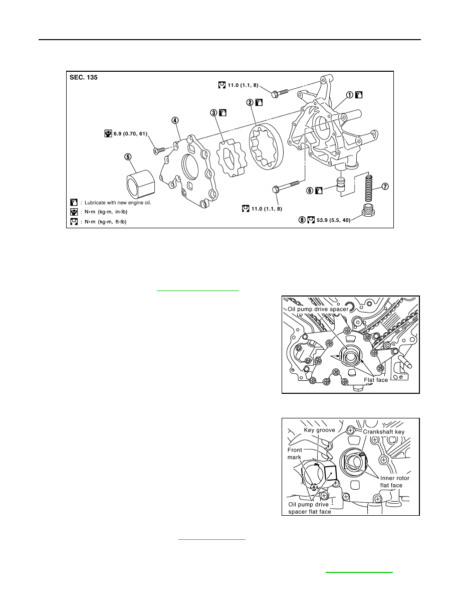
Removal and Installation
INFOID:0000000001297368
REMOVAL
1.
Remove front cover. Refer to
2.
Remove the oil pump drive spacer.
3.
Remove the oil pump assembly.
INSTALLATION
Installation is in the reverse order of removal, paying attention of the following:
• When inserting the oil pump drive spacer, align the crankshaft key
and the flat face of the inner rotor.
• If they are not aligned, rotate the oil pump inner rotor by hand.
• Make sure that each part is aligned and tap lightly until it reaches
the end.
INSPECTION AFTER INSTALLATION
1.
Check the engine oil level. Refer to
2.
Start the engine and check for engine oil leaks.
3.
Stop the engine and wait 10 minutes.
4.
Check the engine oil level and adjust the engine oil level as required. Refer to
.
WBIA0415E
1.
Oil pump body
2.
Outer rotor
3.
Inner rotor
4.
Oil pump cover
5.
Oil pump drive spacer
6.
Regulator valve
7.
Regulator spring
8.
Regulator plug
KBIA2512E
KBIA2490E

OIL PUMP
LU-31
< ON-VEHICLE REPAIR >
[VK56DE]
C
D
E
F
G
H
I
J
K
L
M
A
LU
N
P
O

LU-32
< DISASSEMBLY AND ASSEMBLY >
[VK56DE]
OIL PUMP
DISASSEMBLY AND ASSEMBLY
OIL PUMP
Disassembly and Assembly
INFOID:0000000001297369
DISASSEMBLY
1.
Remove oil pump cover.
2.
Remove inner rotor and outer rotor from oil pump body.
3.
Remove the regulator valve plug, regulator valve spring and regulator valve.
INSPECTION AFTER DISASSEMBLY
Clearance of Oil Pump Parts
• Measure radial clearance using a suitable tool.
• Measure side clearance using suitable tools.
• Calculate the clearance between inner rotor and oil pump body as
follows.
1.
Measure the outer diameter of protruded portion of inner rotor
(position 5) using suitable tool.
Body to outer rotor (position 1)
: 0.114 - 0.200 mm (0.0045 - 0.0079 in)
Inner rotor to outer rotor tip (position 2)
: Below 0.180 mm (0.0071 in)
PBIC0139E
Body to inner rotor (position 3)
: 0.030 - 0.070 mm (0.0012 - 0.0028 in)
Body to outer rotor (position 4)
: 0.030 - 0.090 mm (0.0012 - 0.0035 in)
PBIC0140E
PBIC0141E

OIL PUMP
LU-33
< DISASSEMBLY AND ASSEMBLY >
[VK56DE]
C
D
E
F
G
H
I
J
K
L
M
A
LU
N
P
O
2.
Measure the inner diameter of oil pump body to brazed portion
(position 6) using suitable tool.
3.
Calculate the clearance using the following formula.
• (Clearance) = (Inner diameter of oil pump body) - (Outer diameter of inner rotor)
Regulator Valve Clearance
Check regulator valve to oil pump cover clearance using the following formula.
• (Clearance) = D
1
(Valve hole diameter) - D
2
(Outer Diameter of
valve)
CAUTION:
• Coat regulator valve with engine oil.
• Check that it falls smoothly into the regulator valve hole by its
own weight.
ASSEMBLY
Installation is in the reverse order of removal.
NOTE:
Install the inner rotor and outer rotor with the punched marks on the
oil pump cover side.
PBIC0142E
Inner rotor to brazed portion of housing
clearance
: 0.045 - 0.091 mm (0.0018 - 0.0036 in)
Regulator valve to oil pump cover
: 0.040 - 0.097 mm (0.0016 - 0.0038 in)
PBIC0143E
PBIC0144E
Нет комментариевНе стесняйтесь поделиться с нами вашим ценным мнением.
Текст