Isuzu Rodeo UE. Manual — part 90
TRANSFER CASE
4D–23
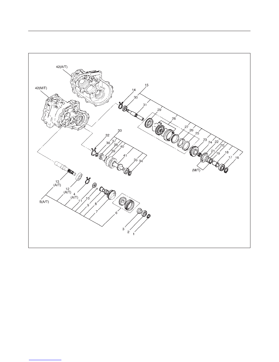
Transfer Case Assembly
Disassembled View
226RW209
Legend
(1) Bearing Snap Ring
(2) Ball Bearing
(3) Lock Nut
(4) Snap Ring (A/T)
(5) Input Shaft Assembly (A/T)
(6) High–Low Clutch Hub and Sleeve
(7) Transfer Input Gear
(8) Needle Bearing
(9) Bearing Collar
(10) Ball
(11) Plate
(12) Ball Bearing (A/T)
(13) Input Shaft (A/T)
(14) Bearing Snap Ring
(15) Front Output Gear Assembly
(16) Bearing Snap Ring
(17) Ball Bearing
(18) Bearing Collar
(19) Sub–Gear Snap Ring (M/T)
(20) Spacer (M/T)
(21) Belleville Spring (M/T)
(22) Sub–Gear (anti–lash plate) (M/T)
(23) Front Output Gear
(24) Needle Bearing
(25) Inside Ring
(26) Outside Ring
(27) Block Ring
(28) 2WD–4WD Clutch Hub and Sleeve Assembly
(29) Stopper Plate
(30) Ball Bearing
(31) Front Output Shaft
4D–24
TRANSFER CASE
(32) Bearing Snap Ring
(33) Counter Gear Assembly
(34) Snap Ring
(35) Ball Bearing
(36) Snap Ring
(37) Ball Bearing
(38) Spacer
(39) Belleville Spring
(40) Sub–Gear (anti–lash plate)
(41) Counter Gear
(42) Transfer Case (with oil seal)
Disassembly
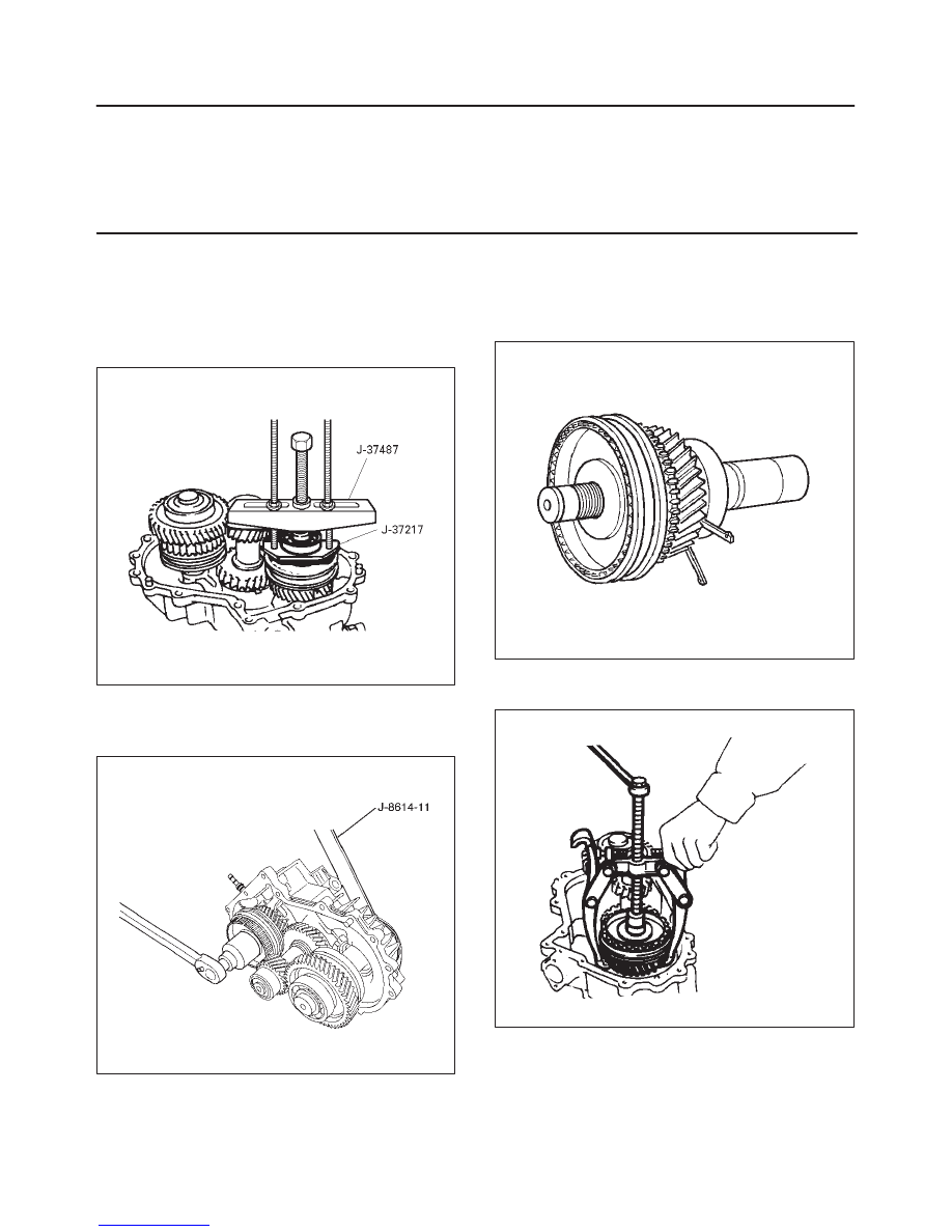
1. Use a pair of snap ring pliers to remove the snap ring
(1).
2. Use a bearing remover J–37217 and puller J–37487
to remove the ball bearing (2).
262RW016
3. Install the front companion flange temporarily.
4. Use the Companion flange holder J–8614–11 and
lock nut wrench J–37219 to remove the lock nut (3).
226RX001
5. Remove the front companion flange.
6. Remove snap ring (4). (A/T)
7. Remove the input shaft assembly (5) from the
transfer case (42). (A/T)
265RW001
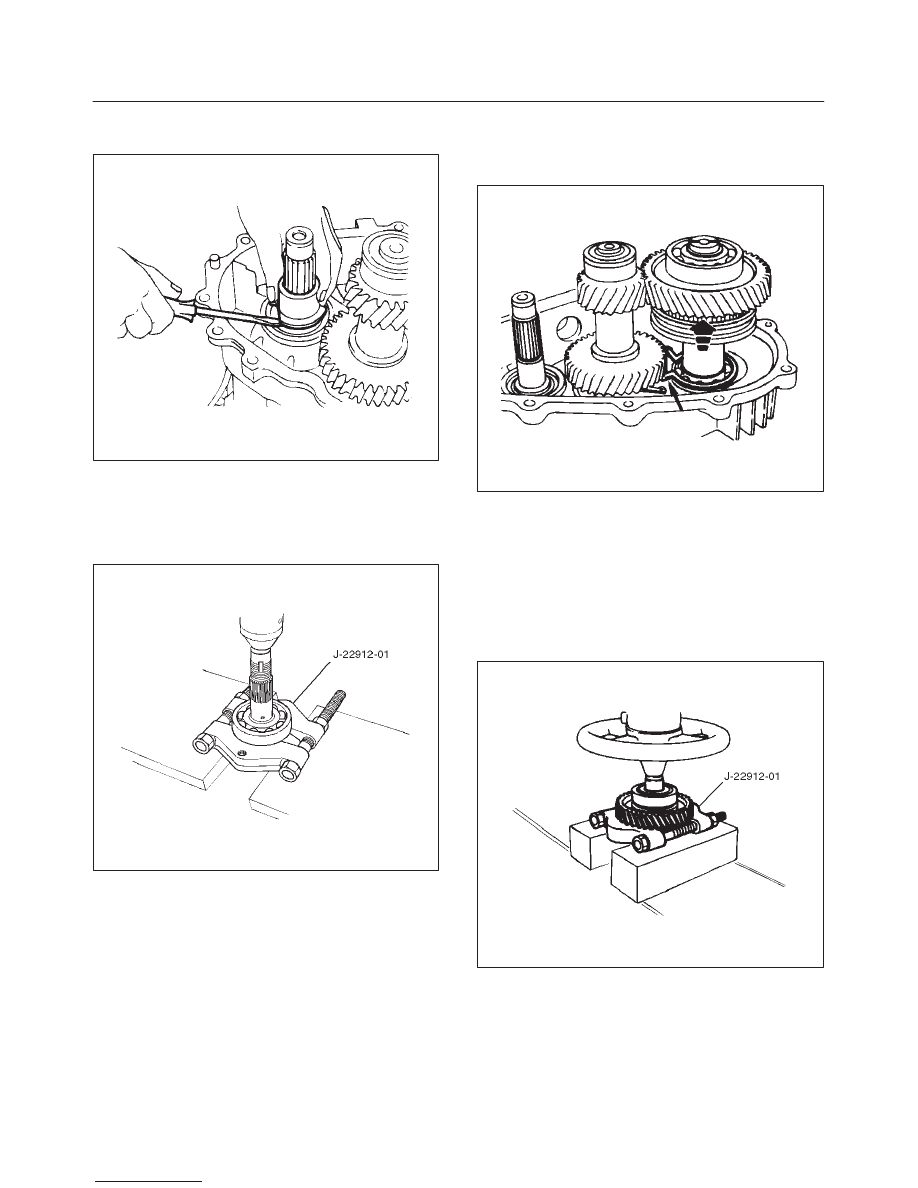
8. Use the universal puller to remove the high–low
clutch hub and sleeve (6), and transfer input gear (7).
226RS070
TRANSFER CASE
4D–25
9. Remove needle bearing (8).
10. Remove bearing collar (9).
226RS071
11. Remove ball (10).
12. Remove plate (11).
13. Use a bench press and the ball bearing remover
J–22912–01 to remove the ball bearing (12) from the
input shaft (13). (A/T)
265RS002
14. Use a pair of snap ring pliers to remove the bearing
snap ring (14).
15. Use a plastic hammer to tap the front output gear
assembly (15) free.
262RS009
16. Remove bearing snap ring (16).
17. Use a bench press and the bearing remover
J–22912–01 to remove the following parts.
18. Remove ball bearing (17), and bearing collar (18).
Remove sub–gear snap ring (19), spacer (20),
belleville spring (21), and sub–gear (anti–lash plate)
(22). (M/T)
Remove front output gear (23) and needle bearing
(24).
262RS010
19. Remove inside ring (25).
20. Remove outside ring (26).
21. Remove block ring (27).
22. Use a bench press and bearing remover J–22912–01
to remove 2WD–4WD clutch hub and sleeve
assembly (28) and stopper plate (29).
NOTE: Do not reuse the stopper plate.
4D–26
TRANSFER CASE
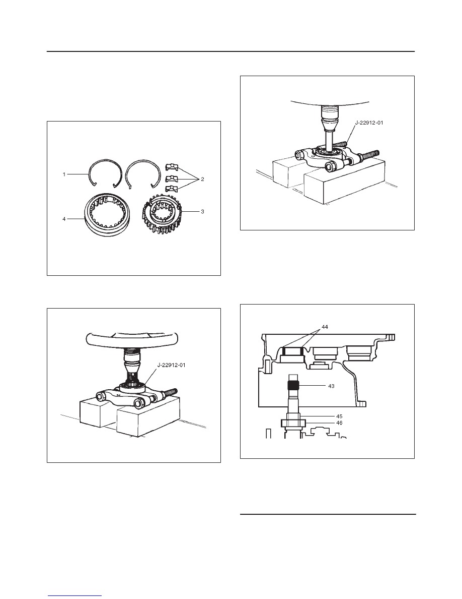
23. Disassemble the 2WD–4WD clutch hub and sleeve
assembly (28).
f
Springs (1)
f
Inserts (2)
f
Clutch Hub (3)
f
Sleeve (4)
226RW133
24. Use a bench press and the ball bearing remover
J–22912–01 to remove the ball bearing (30) from
front output shaft (31).
262RS011
25. Remove bearing snap ring (32).
26. Remove the counter gear assembly (33) from the
transfer case (42).
27. Use a pair of snap ring pliers to remove the snap ring
(34).
28. Use a bench press and the bearing remover
J–22912–01 to remove the ball bearing (35).
29. Use a pair of snap ring pliers to remove the snap ring
(36).
30. Use a bench press and the bearing remover
J–22912–01 to remove the ball bearing (37).
226RS073
31. Remove spacer (38).
32. Remove belleville spring (39).
33. Remove sub–gear (anti–lash plate) (40).
34. Remove counter gear (41).
35. Remove transfer case (with oil seal) (42), performing
the following steps (M/T)
f
Cover the shaft splines with adhesive tape (43).
A07RW022
Legend
(43) Adhesive Tape
(44) Oil Seal Lip
(45) Oil Seal Collar
(46) Bearing
f
Remove the transfer case together with
intermediate plate with gear assembly from the
transmission case (M/T).
Нет комментариевНе стесняйтесь поделиться с нами вашим ценным мнением.
Текст