Isuzu Rodeo UE. Manual — part 187

6E1–119
RODEO X22SE 2.2L ENGINE DRIVEABILITY AND EMISSION
DTC P0108 MAP Sensor Circuit High Input
(Cont'd)
Step
No
Yes
Value(s)
Action
8
1. Ignition OFF.
2. Place a fused jumper between the MAP sensor
circuit and the 5 volt signal circuit, both at the wiring
harness’ MAP sensor connector.
3. Ignition ON, Engine OFF.
4. Observe the MAP value displayed on the Tech 2?
Does the Tech 2 read the following value?
5 volts 104
kPa
Go to Step 9
Go to Step 12
9
Check the MAP sensor ground circuit, between the
MAP sensor and the PCM, for the following conditions:
f
An open circuit
f
A short to ground
f
A short to voltage
Was the problem found?
—
Verify repair
Go to Step 10
10
1. Ignition OFF.
2. Place a Digital Multimeter (DVM), set to measure
voltage, between the ground circuit and the 5 volt
signal circuit, both at the wiring harness’ MAP
sensor connector.
3. Ignition ON, Engine OFF.
Does the DVM read the following value?
5 Volts
Go to Step 11
Go to Step 12
11
Replace the MAP sensor.
Verify repair.
—
—
—
12
Replace the PCM.
IMPORTANT: The replacement PCM must be
programmed. Refer to On–Vehicle Service in
Powertrain Control Module and Sensors for
procedures.
And also refer to latest Service Bulletin.
Check to see if the Latest software is released or not.
And then Down Load the LATEST PROGRAMMED
SOFTWARE to the replacement PCM.
Verify repair.
—
—
—
6E1–120
RODEO X22SE 2.2L ENGINE DRIVEABILITY AND EMISSION
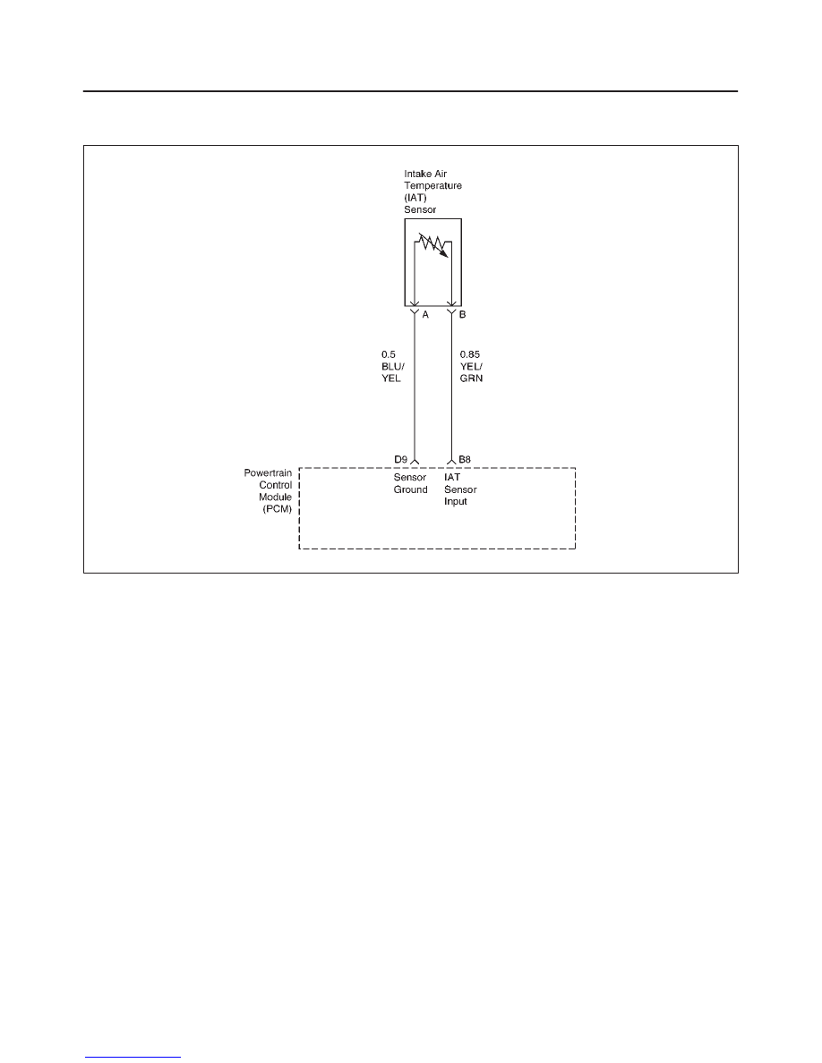
DIAGNOSTIC TROUBLE CODE (DTC) P0112 INTAKE AIR TEMPERATURE (IAT)
SENSOR CIRCUIT LOW INPUT
D06RX043
Circuit Description
The intake air temperature (IAT) sensor is a thermistor
which measures the temperature of the air entering the
engine. The powertrain control module (PCM) applies 5
volts through a pull–up resistor to the IAT sensor. When
the intake air is cold, the sensor resistance is high and the
PCM will monitor a high signal voltage on the IAT signal
circuit. If the intake air is warm, the sensor resistance is
lower, causing the PCM to monitor a lower voltage.
Diagnostic Trouble Code P0112 will set when the PCM
detects an excessively low signal voltage (short to
ground) on the intake air temperature sensor signal
circuit. DTC P0112 is a Type A Code.
Conditions for Setting the DTC
f
The engine has been running for over 2 minutes.
f
Vehicle speed is greater than 48 km/h (30 mph).
f
IAT signal voltage less than 0.10 volts for a total of 12.5
seconds over a 25–second period of time.
The above conditions are met for at least 2 seconds.
Action Taken When the DTC Sets
f
The PCM will illuminate the malfunction indicator lamp
(MIL) the first time the fault is detected.
f
The PCM will use a default IAT valve based on PCM
inputs and engine run time.
f
The PCM will store conditions which were present
when the DTC was set as Freeze Frame and in the
Failure Records data.
Conditions for Clearing the MIL/DTC
f
The PCM will turn the MIL OFF on the third consecutive
trip cycle during which the diagnostic has been run and
the fault condition is no longer present.
f
A history DTC P0112 will clear after 40 consecutive
warm–up cycles have occurred without a fault.
f
DTC P0112 can be cleared by using the Scan Tool’s
”Clear Info” function.
Diagnostic Aids
Check for the following conditions:
f
Poor connection at PCM – Inspect harness connectors
for backed–out terminals, improper mating, broken
locks, improperly formed or damaged terminals, and
poor terminal–to–wire connection.
f
Damaged harness – Inspect the wiring harness for
damage, shorts to ground, shorts to battery and open
circuits. If the harness appears to be OK, observe the
IAT display on the Tech 2 while moving connectors and
wiring harnesses related to the IAT sensor. A change
in the IAT display will indicate the location of the fault.
If Diagnostic Trouble Code P0112 cannot be duplicated,
the information included in the Failure Records data can
be useful in determining vehicle mileage since the
Diagnostic Trouble Code was last set.

6E1–121
RODEO X22SE 2.2L ENGINE DRIVEABILITY AND EMISSION
Test Description
Number(s) below refer to the step number(s) on the
Diagnostic Chart:
2. Verifies that the fault is present.
3. If Diagnostic Trouble Code P0112 can be repeated
only by duplicating the Failure Records condition,
refer to the Temperature vs. Resistance Value table.
The table may be used to test the IAT sensor at
various temperatures to evaluate the possibility of
a ”shifted” sensor that may be stored above or
below a certain temperature. If this is the case,
replace the IAT sensor. If the IAT sensor appears
to be OK, the fault is intermittent; refer to
Diagnostic Aids.
Intake Air Temperature Sensor
°
C
°
F
OHMS
Temperature vs. Resistance Values (approximate)
100
212
177
80
176
332
60
140
667
45
113
1188
35
95
1802
25
77
2796
15
59
4450
5
41
7280
–5
23
12300
–15
5
21450
–30
–22
52700
–40
–40
100700

6E1–122
RODEO X22SE 2.2L ENGINE DRIVEABILITY AND EMISSION
DTC P0112 Intake Air Temperature (IAT) Sensor Circuit Low Input
Step
Action
Value(s)
Yes
No
1
Was the ”On–Board Diagnostic (OBD) System Check”
performed?
—
Go to Step 2
Go to OBD
System
Check
2
1. Ignition ON, engine OFF.
2. Using a Tech 2, monitor the intake air temperature
(IAT).
Is the intake air temperature greater than the specified
value?
148
°
C
(283
°
F)
Go to Step 4
Go to Step 3
3
1. Ignition ON, engine OFF. Review and record Tech 2
Failure Records data.
2. Operate the vehicle within Failure Records
conditions as noted.
3. Using a Tech 2, monitor the ”DTC” info for
Diagnostic Trouble Code P0112.
Does the Tech 2 indicate DTC P0112 failed this
ignition?
—
Refer to Test
Description
Refer to
Diagnostic
Aids
4
1. Ignition OFF.
2. Disconnect the IAT sensor electrical connector.
3. Ignition ON.
4. Observe the intake air temperature on the Tech 2.
Is the intake air temperature below the specified value?
–38
°
C
(–36
°
F)
Go to Step 6
Go to Step 5
5
1. Ignition OFF.
2. Disconnect the PCM electrical connectors.
3. Check the IAT sensor signal circuit for a short to
ground.
Is the IAT sensor signal circuit shorted to ground?
—
Verify Repair
Go to Step 7
6
Replace the IAT sensor.
Is the action complete?
—
Verify Repair
—
7
Replace the PCM.
IMPORTANT: The replacement PCM must be
programmed. Refer to On–Vehicle Service in
Powertrain Control Module and Sensors for
procedures.
And also refer to latest Service Bulletin.
Check to see if the Latest software is released or not.
And then Down Load the LATEST PROGRAMMED
SOFTWARE to the replacement PCM.
Is the action complete?
—
Verify Repair
—
Нет комментариевНе стесняйтесь поделиться с нами вашим ценным мнением.
Текст