Isuzu Rodeo UE. Manual — part 288
6A–65
ENGINE MECHANICAL (6VD1 3.2L)
Reassembly
1. Install camshaft drive gear assembly and tighten
three bolts to specified torque.
Torque: 10 N·m (89 lb in)
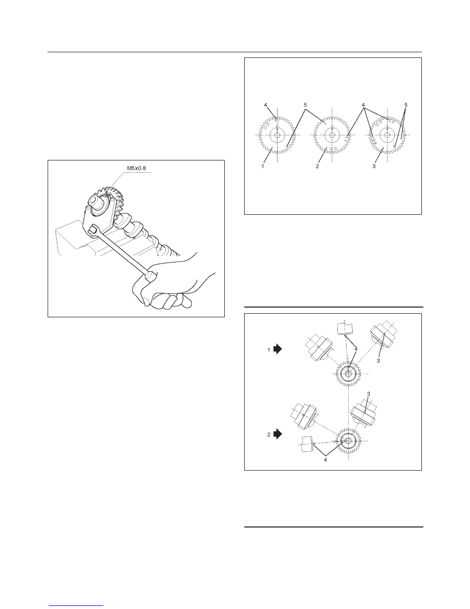
2. Tighten sub gear setting bolt.
1. Use J–42686 to turn sub gear to right direction
until the M5 bolt hole aligns between camshaft
driven gear and sub gear.
2. Tighten M5 bolt suitable torque for prevent
moving the sub gear.
014RW041
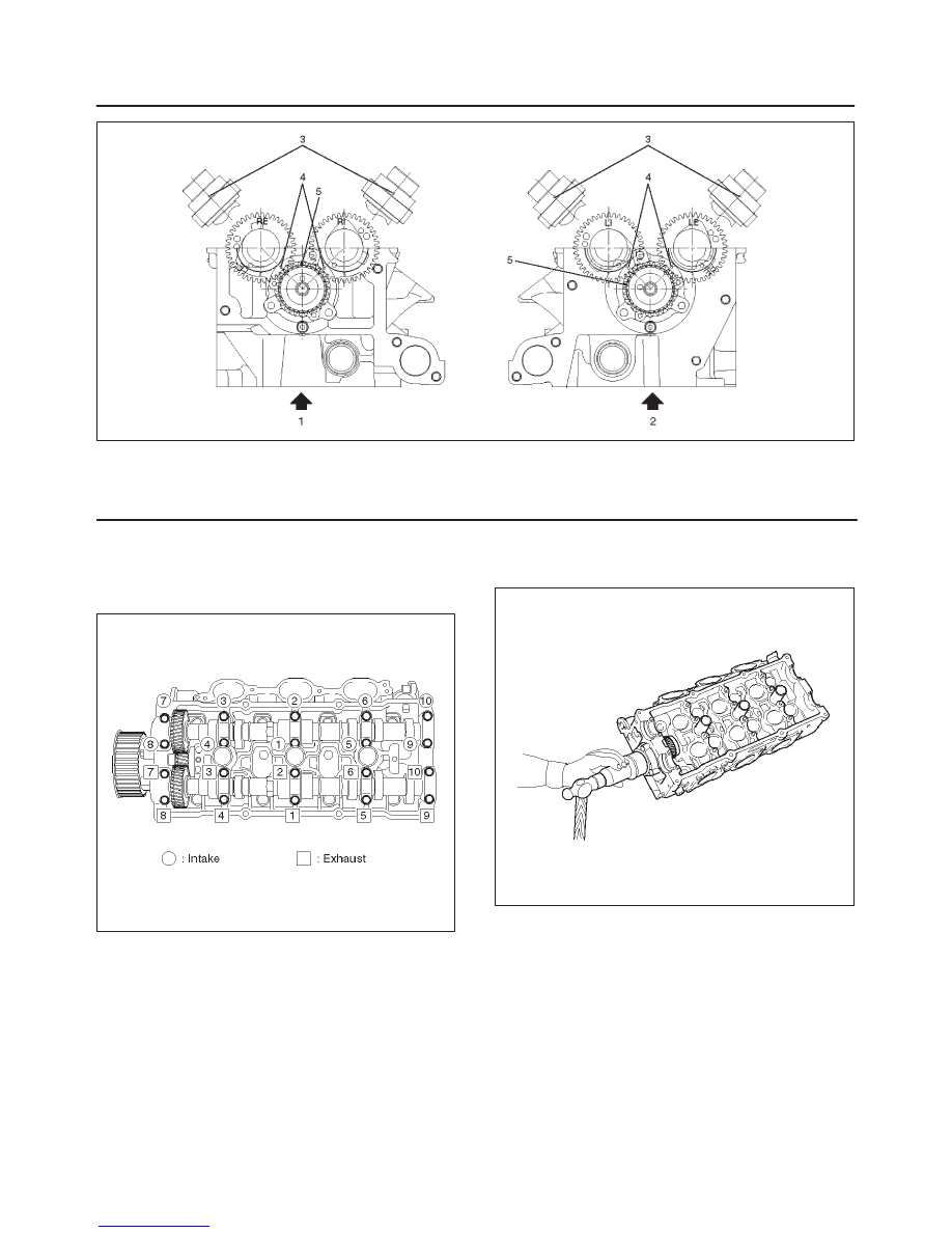
3. Install camshaft assembly and camshaft brackets,
tighten twenty bolts on one side bank to the specified
torque.
1. Apply engine oil to camshaft journal and bearing
surface of camshaft bracket.
2. Align timing mark on intake camshaft (one dot for
right bank, two dots for left bank) and exhaust
camshaft (one dot for right bank, two dots for left
bank) to timing mark on camshaft drive gear (one
dot).
014RW020
Legend
(1) Intake Camshaft Timing Gear for Right Bank
(2) Intake Camshaft Timing Gear for Left Bank
(3) Exhaust Camshaft Timing Gear
(4) Discerning Mark
LI: Left Bank Intake
RI: Right Bank Intake
LE: Left Bank Exhaust
RE: Right Bank Exhaust
014RW023
Legend
(1) Right Bank Camshaft Drive Gear
(2) Left Bank Camshaft Drive Gear
(3) Timing Mark on Drive Gear
(4) Dowel Pin
6A–66
ENGINE MECHANICAL (6VD1 3.2L)
014RW024
Legend
(1) Right Bank
(2) Left Bank
(3) Alignment Mark on Camshaft Drive Gear
(4) Alignment Mark on Camshaft
(5) Alignment Mark on Retainer
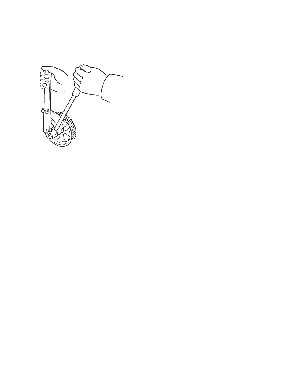
3. Tighten twenty bolts in numerical order on one
side bank as shown in the illustration.
Torque: 10 N·m (89 lb in)
014RW031
4. If the oil seal requires replacement, use the J–42985
to install the oil seal.
014RW034
6A–67
ENGINE MECHANICAL (6VD1 3.2L)
5. Tighten bolt for camshaft drive gear assembly pulley
to the specified torque using the J–43041 universal
holder.
Torque: 98 N·m (72 lb ft)
014RW060
6A–68
ENGINE MECHANICAL (6VD1 3.2L)
Crankshaft
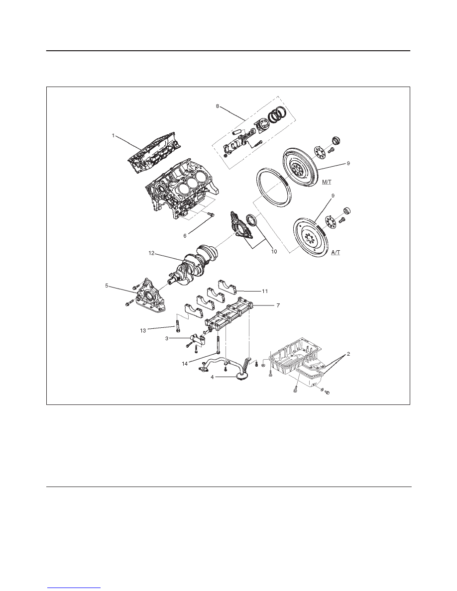
Crankshaft and Associated Parts
013RW009
Legend
(1) Cylinder Head Assembly
(2) Crankcase with Oil Pan
(3) Oil Pipe and O-ring
(4) Oil Strainer and O-ring
(5) Oil Pump Assembly
(6) Cylinder Block Side Bolts
(7) Oil Gallery
(8) Piston and Connecting Rod Assembly
(9) Flywheel
(10) Rear Oil Seal Retainer and Oil Seal
(11) Main Bearing Cap
(12) Crankshaft
(13) Main Bearing Cap Fixing Bolts
(14) Oil Gallery Fixing Bolts
Disassembly
1. Remove cylinder head assembly (1). Refer to
“Cylinder Head” in this manual.
2. Remove crankcase with oil pan (2). Refer to “Oil Pan
and Crankcase” in this manual.
CAUTION: Take care not to damage or deform the
sealing flange surface of crankcase.
3. Remove oil pipe and O-ring (3).
4. Remove oil strainer and O-ring (4).
5. Remove oil pump assembly (5).
6. Remove crankcase side bolts (6).
Нет комментариевНе стесняйтесь поделиться с нами вашим ценным мнением.
Текст