
Chrysler Stratus Convertible. Manual — part 371
(12) Remove refrigerant from air conditioning sys-
tem using a refrigerant recovery machine. Refer to
Group 24, Air Conditioning for procedure.
(13) Hoist vehicle and remove right inner splash
shield.
(14) Remove accessory drive belts. Refer to Group
7, Cooling System for procedure.
(15) Remove axle shafts. Refer to Group 2, Suspen-
sion and Driveshaft for procedure.
(16) Disconnect exhaust pipe from manifold.
(17) Remove front and rear engine mount through
bolts.
(18) Lower vehicle. Remove air cleaner assembly.
(19) Remove power steering pump and reservoir
and set them aside.
(20) Remove A/C compressor.
(21) Remove ground straps to body.
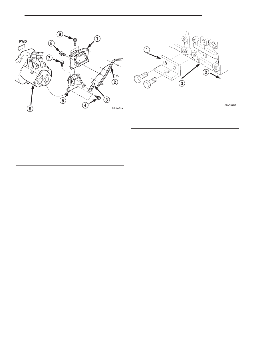
(22) Mount Special Tool 6973 bracket, to the right
side of the cylinder block (Fig. 34). Align the front
adjustable post with the hole in the bracket.
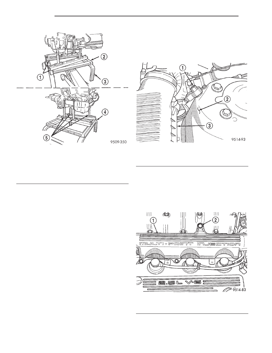
(23) Raise vehicle enough to allow engine dolly
and cradle Special Tools 6135 and 6710 to be
installed under vehicle (Fig. 35).
(24) Loosen cradle engine mounts to allow move-
ment for positioning onto engine locating holes on the
engine bedplate. Lower vehicle and position cradle
mounts until the engine is resting on mounts. Tighten
mounts to cradle frame. This will keep mounts from
moving when removing or installing engine and tran-
saxle.
(25) Lower vehicle so weight of the engine and
transaxle ONLY is on the cradle.
(26) Remove engine and transaxle mount bolts.
(27) Raise vehicle slowly. It may be necessary to
move the engine/transaxle assembly on the cradle to
allow for removal around body flanges.
INSTALLATION
(1) Position engine/transaxle assembly under vehi-
cle and slowly lower the vehicle.
(2) Align engine and transaxle mounts to attach-
ing points. Install mounting bolts at the right engine
and left transaxle mounts. Refer to procedures in this
section.
(3) Slowly raise vehicle enough to remove the
engine dolly and cradle Special Tools 6135 and 6710.
(4) Remove Special Tool 6973 bracket from engine.
(5) Install axle shafts. Refer to Group 2, Suspen-
sion and Driveshaft for procedure.
(6) Install transaxle and engine braces.
(7) Connect exhaust system to manifold.
(8) Install power steering pump and reservoir.
Refer to Group 7, Cooling System Accessory Drive
Section for belt tension adjustment.
(9) Install A/C compressor and hoses. Refer to
Group 24, Heater and Air Conditioning for procedure.
(10) Install accessory drive belts. Refer to Group 7,
Cooling System Accessory Drive Section for belt ten-
sion adjustment.
(11) Install front and rear engine mounts. Refer to
procedure in this section.
(12) Install inner splash shield. Install wheels and
tires.
Fig. 33 Left Side Mount—Typical
1 – TRANSMISSION SUPPORT ASSEMBLY
2 – LEFT FRAME RAIL
3 – GROUND CABLE
4 – BOLT (D)
5 – TRANSMISSION BRACKET
6 – TRANSMISSION
7 – BOLT (C)
8 – BOLT (B)
9 – BOLT (A)
Fig. 34 Bracket for Cradle Post Support
1 – SPECIAL TOOL 6973
2 – FRONT OF ENGINE
3 – OIL PAN MATTING SURFACE
JX
ENGINE
9 - 25
REMOVAL AND INSTALLATION (Continued)
(13) Connect automatic transaxle cooler lines and
shifter linkage. Refer to Group 21, Transaxle for pro-
cedures.
(14) Connect fuel line and heater hoses.
(15) Install ground straps. Connect engine and
throttle body connections and wiring harnesses.
Refer to Group 8, Electrical for procedure.
(16) Connect throttle body linkage. Refer to Group
14, Fuel System for procedure.
(17) Install radiator and shroud assembly. Install
radiator hoses. Fill cooling system. See Group 7,
Cooling System for filling procedure.
(18) Connect battery.
(19) Install Powertrain Control Module (PCM).
(20) Install air cleaner and hoses.
(21) Install oil filter. Fill engine crankcase with
proper oil to correct level.
(22) Evacuate and charge air conditioning system.
Refer to Group 24, Heating and Air Conditioning for
procedures.
(23) Start engine and run until operating temper-
ature is reached.
(24) Adjust transaxle linkage, if necessary.
INTAKE MANIFOLD—UPPER
REMOVAL
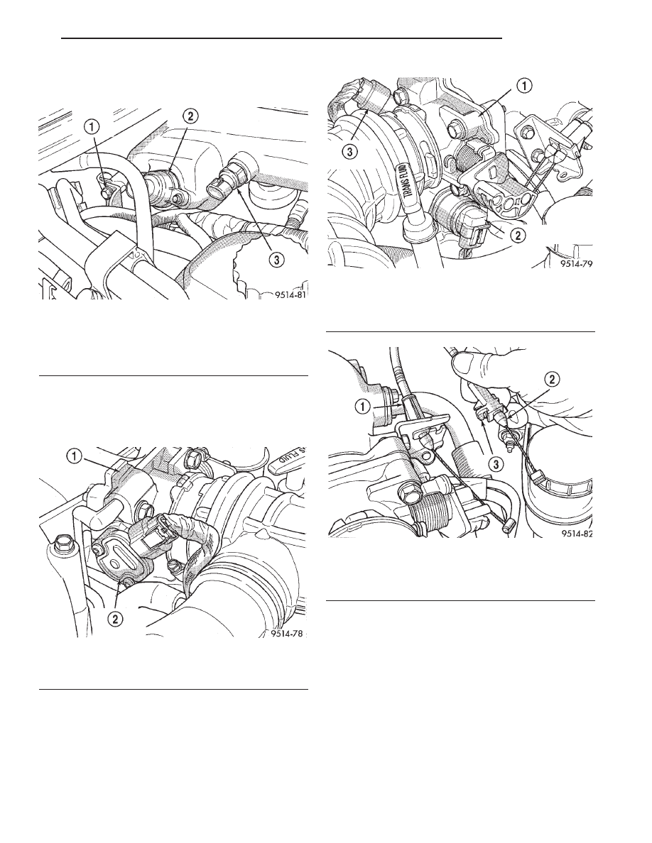
(1) Disconnect
negative
cable
from
auxiliary
jumper terminal (Fig. 36).
(2) Remove bolt holding air inlet resonator to
intake manifold (Fig. 37).
(3) Loosen throttle body air inlet hose clamp.
(4) Release snaps holding air cleaner housing
cover to housing.
(5) Remove air cleaner cover and inlet hoses from
engine.
(6) Disconnect connectors from MAP and intake
air temperature sensors (Fig. 38).
Fig. 35 Positioning Engine Cradle Support Post
Mounts
1 – SPECIAL TOOL SUPPORT BARS NO. 6810-3A
2 – SPECIAL TOOL ENGINE CRADLE NO. 6810
3 – SPECIAL TOOL ENGINE DOLLY NO. 6135
4 – SPECIAL TOOL ENGINE CRADLE NO. 6810
5 – SPECIAL TOOL ADJUSTABLE POSTS NO. 6848
Fig. 36 Auxiliary Jumper Terminal
1 – AUXILIARY JUMPER TERMINAL
2 – LEFT STRUT TOWER
3 – AIR CLEANER HOUSING
Fig. 37 Air Inlet Resonator
1 – AIR INLET RESONATOR
2 – RESONATOR BOLT
9 - 26
ENGINE
JX
REMOVAL AND INSTALLATION (Continued)
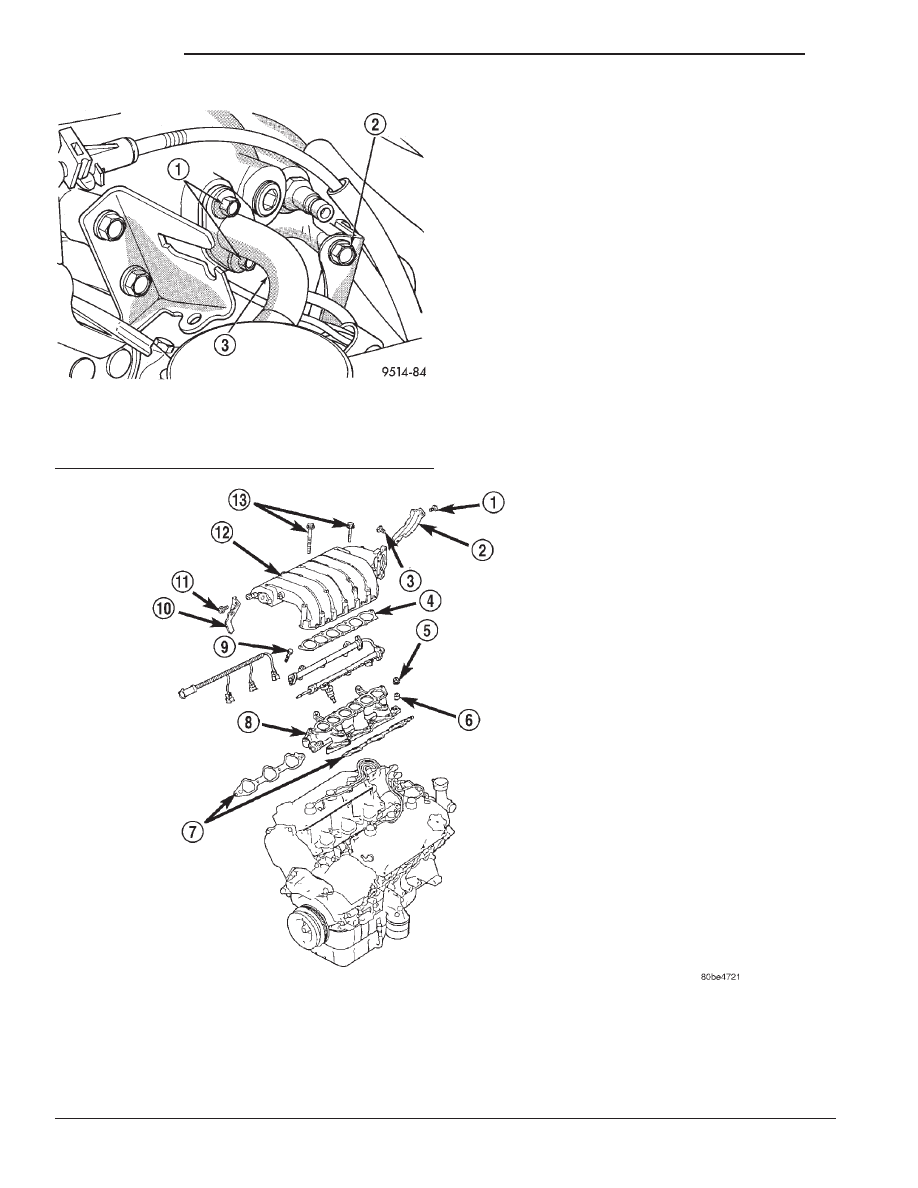
(7) Remove manifold support bracket bolt located
rearward of MAP sensor (Fig. 38).
(8) Disconnect TPS and idle air control motor con-
nectors (Fig. 39) and (Fig. 40).
(9) Disconnect brake booster hose.
(10) Disconnect purge hose from throttle body.
(11) Squeeze retainer tab on throttle cable and
slide cable out of bracket (Fig. 41).
(12) Slide speed control cable out of bracket, if
equipped (Fig. 41).
(13) Remove EGR tube from intake manifold and
discard gasket (Fig. 42).
(14) Remove manifold support bracket bolt located
rearward of EGR tube (Fig. 42).
(15) Remove bolts holding upper intake manifold
and remove manifold (Fig. 43).
Fig. 38 Intake Manifold Sensors and Left Manifold
Support Bolt
1 – SUPPORT BRACKET BOLT
2 – MAP SENSOR
3 – INTAKE AIR TEMPERATURE SENSOR
Fig. 39 Throttle Position Sensor
1 – THROTTLE BODY
2 – THROTTLE POSITION SENSOR
Fig. 40 Idle Air Control Motor
1 – THROTTLE BODY
2 – IDLE AIR CONTROL MOTOR
3 – THROTTLE POSITION SENSOR
Fig. 41 Throttle Cable Attachment
1 – SPEED CONTROL CABLE
2 – THROTTLE CABLE
3 – RELEASE TANG
JX
ENGINE
9 - 27
REMOVAL AND INSTALLATION (Continued)
INSTALLATION
(1) Install new gasket and position upper intake
manifold to lower manifold. Install manifold bolts
and tighten to 18 N·m (13 ft. lbs.) (Fig. 43).
(2) Install bolts at manifold support brackets.
Tighten bolts to 18 N·m (13 ft. lbs.).
(3) Install EGR tube with new gasket to plenum.
Tighten EGR tube to intake manifold plenum screws
to 11 N·m (95 in. lbs.).
(4) Install throttle and speed control cables.
(5) Connect brake booster hose.
(6) Connect purge hose to throttle body.
(7) Attach electrical connectors to sensors.
(8) Install air cleaner cover and inlet hoses.
(9) Tighten air inlet tube clamps to 3 N·m
61 (25
in. lbs.
65).
(10) Install bolt holding air inlet resonator to
intake manifold (Fig. 37).
(11) Connect negative cable to auxiliary jumper
terminal (Fig. 36).
Fig. 42 EGR Tube and Right Manifold Support Bolt
1 – EGR TUBE BOLTS
2 – SUPPORT BRACKET BOLT
3 – EGR TUBE
Fig. 43 Intake Manifolds
1 – 18 N
•
m (13 ft. lbs.)
2 – LEFT SIDE MANIFOLD SUPPORT
3 – 36 N
•
m (26 ft. lbs.)
4 – GASKET
5 – NUT
6 – SPRING WASHER
7 – LOWER INTAKE MANIFOLD GASKETS
8 – LOWER INTAKE MANIFOLD
9 – 12 N
•
m (8 ft. lbs.)
10 – RIGHT SIDE MANIFOLD SUPPORT
11 – 18 N
•
m (13 ft. lbs.)
12 – UPPER INTAKE MANIFOLD
13 – 18 N
•
m (13 ft. lbs.)
9 - 28
ENGINE
JX
REMOVAL AND INSTALLATION (Continued)
Нет комментариевНе стесняйтесь поделиться с нами вашим ценным мнением.
Текст