
Chrysler Stratus Convertible. Manual — part 378
(2) Install valve spring seat.
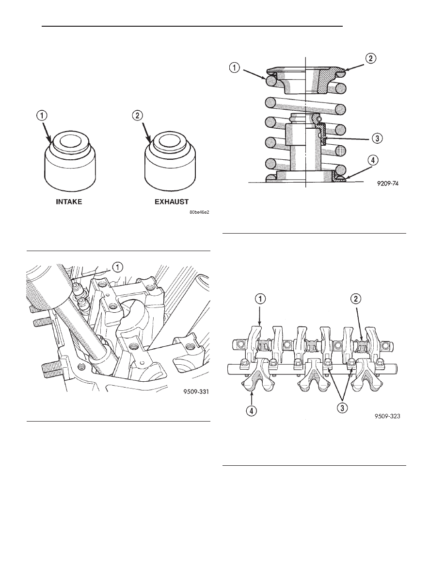
(3) Install the “gray” valve seal onto the intake
valve and the “grayish green” seal onto the exhaust
valve (Fig. 110). Using Special Tool MD-998774
install seal by tapping lightly until seal is in place
(Fig. 111).
(4) Install valve spring with the enamelled ends
facing the rocker arms (Fig. 112). Install valve
springs and retainers. Compress valve springs only
enough to install locks, taking care not to misalign
the direction of compression. Nicked valve stems may
result from misalignment of the valve spring com-
pressor.
CAUTION: When
depressing
the
valve
spring
retainers with valve spring compressor the locks
can become dislocated. Check to make sure both
locks are in their correct location after removing
tool.
ROCKER ARMS
(1) Identify the rocker arms and retainers for reas-
sembly. Disassemble the rocker arm assemblies by
removing the attaching bolts and spring clips from
the shaft (Fig. 113).
(2) Slide the rocker arms off the shaft. Keep the
spacers and rocker arms in the same location for
reassembly.
INSPECTION
Inspect the rocker arm for scoring, wear of the
roller or damage to the rocker arm (Fig. 114).
Replace as necessary.
Fig. 110 Valve Stem Seals Identification
1 – GRAY
2 – GRAYISH GREEN
Fig. 111 Valve Stem Seals—Installed
1 – SPECIAL TOOL MD998774
Fig. 112 Valve Spring Position—Installed
1 – ENAMELED END
2 – SPRING RETAINER
3 – STEM SEAL
4 – SPRING SEAT
Fig. 113 Rocker Arm Shafts
1 – INTAKE ROCKER ARMS
2 – ROCKER SHAFT SPRINGS
3 – ROCKER ARM SHAFT RETAINERS
4 – EXHAUST ROCKER ARMS
JX
ENGINE
9 - 53
DISASSEMBLY AND ASSEMBLY (Continued)
ROCKER ARM SHAFTS
The rocker arm shafts is hollow and is used as a
lubrication oil duct.
(1) Check the rocker arm mounting portion of the
shafts for wear or damage. Replace if damaged or
worn.
(2) Check oil holes for clogging with small wire,
clean as required.
REASSEMBLY
Lubricate the rocker arms. Install onto shafts in
their original position (Fig. 113).
OIL PUMP
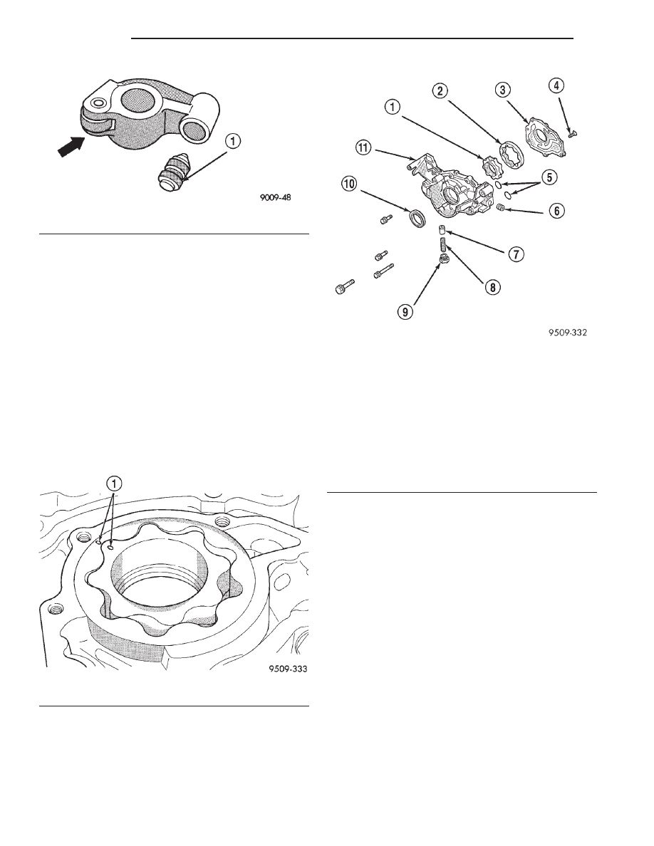
(1) Assemble pump, using new parts as required
with clean oil. Align marks on the inner and outer
rotors when assembling (Fig. 115).
(2) Install cover and tighten screws to 10 N·m (85
in. lbs.).
(3) Install relief valve, spring, gasket and cap as
shown in (Fig. 116). Tighten cap to 44 N·m (33 ft.
lbs.)
CLEANING AND INSPECTION
INTAKE MANIFOLD
CLEANING
Discard gasket and clean all gasket surfaces of
manifold to cylinder heads.
INSPECTION
Check upper and lower manifold gasket surfaces
for flatness with straight edge. Surface must be flat
within 0.15 mm per 300 mm (0.006 in. per foot) of
manifold length.
Inspect manifolds for cracks or distortion. Replace
manifold if necessary.
EXHAUST MANIFOLD
CLEANING
Clean sealing surfaces of manifold and cylinder
head.
Fig. 114 Rocker Arm
1 – AUTO-LASH ADJUSTER
Fig. 115 Inner and Outer Rotor Alignment Marks
1 – ALIGNMENT MARKS
Fig. 116 Oil Pump
1 – INNER ROTOR
2 – OUTER ROTOR
3 – PUMP COVER
4 – SCREW
5 – O-RINGS
6 – PLUG
7 – OIL PRESSURE RELIEF VALVE
8 – RELIEF VALVE SPRING
9 – PLUG
10 – SEAL
11 – OIL PUMP BODY
9 - 54
ENGINE
JX
DISASSEMBLY AND ASSEMBLY (Continued)
INSPECTION
Inspect exhaust manifolds for damage or cracks.
Check distortion of the cylinder head mounting sur-
face and exhaust crossover mounting surface with a
straightedge and thickness gauge.
CAMSHAFT
CLEANING
Clean camshaft with a suitable solvent.
INSPECTION
Check oil feed holes for blockage.
Inspect cylinder head journals for wear.
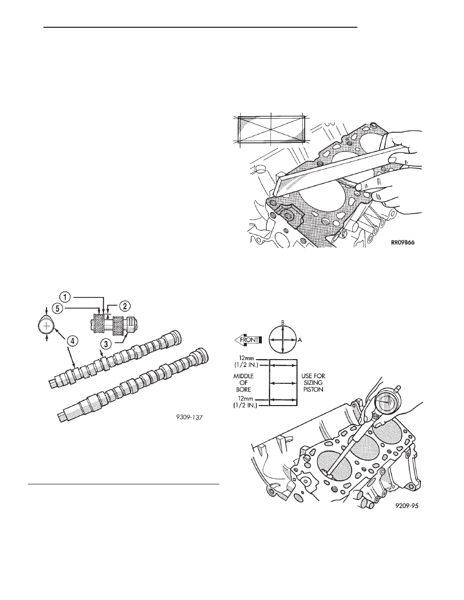
Check camshaft bearing journals for scratches and
worn areas (Fig. 117). If light scratches are present,
they may be removed with 400 grit sand paper. If
deep scratches are present, replace the camshaft and
check the cylinder head for damage. Replace the cyl-
inder head if worn or damaged. Check the lobes for
pitting and wear. If the lobes show signs of wear,
check the corresponding rocker arm roller for wear or
damage. Replace rocker arm if worn or damaged. If
lobes show signs of pitting on the nose, flank or base
circle; replace the camshaft.
CYLINDER BORE AND BLOCK
CLEANING
Clean cylinder block using a suitable solvent.
CYLINDER BLOCK INSPECTION
Inspect cylinder block for scratches, cracks and
rust or corrosion, and repair or replace as required.
(1) Clean cylinder block and check top surface for
distortion with a straight edge and thickness gauge
(Fig. 118).
(2) Top surface must be flat within:
• Standard Value: 0.05 mm (0.002 in.)
• Service Limit 0.1 mm (0.0039 in.)
CYLINDER BORE INSPECTION
(1) Measure the cylinder bore at three levels in
directions A and B (Fig. 119). Top measurement
should be 12 mm (0.50 in.) down and bottom mea-
surement should be 10 mm (0.38 in.) up.
(2) Standard bore dimension: 83.50 - 83.53 mm
(3.2874- 3.2886 in.)
(3) Maximum out-of-round or taper: 0.01 mm
(0.0004 in.)
Fig. 117 Checking Camshafts for Wear
1 – UNWORN AREA - MIKE HERE
2 – ACTUAL WEAR
3 – BEARING JOURNAL
4 – LOBE
5 – WEAR ZONE - MIKE HERE
Fig. 118 Distortion Check
Fig. 119 Checking Cylinder Bore Size
JX
ENGINE
9 - 55
CLEANING AND INSPECTION (Continued)
CYLINDER HEAD
CLEANING
Clean cylinder head and oil passages using a suit-
able solvent.
INSPECTION
CYLINDER HEAD
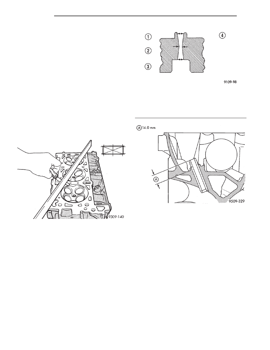
Check cylinder head for flatness (Fig. 120).
Cylinder head must be flat within:
• Standard dimension: less than 0.03 mm (0.0012
inch)
• Service Limit: 0.2 mm (0.008 inch)
• Grinding Limit: Maximum of 0.2 mm (0.008
inch) is permitted.
CAUTION: This is a combined total dimension of
stock removal from cylinder head if any and block
top surface is 0.2 mm (0.0079 in.).
VALVE GUIDES
Remove carbon and varnish deposits from inside of
valve guides with a reliable guide cleaner.
Using a small hole gauge and a micrometer, mea-
sure valve guides in 3 places top, middle and bottom
(Fig. 121). Refer to Engine Specifications. Replace
guides if they are not within specification.
Check valve guide height (Fig. 122).
CYLINDER HEAD COVER
CLEANING
Clean cylinder head and cover mating surfaces
using a suitable solvent.
INSPECTION
Inspect cover rails for flatness.
ROCKER ARM AND AUTO LASH ADJUSTER
CLEANING
The automatic lash adjusters are precision units
installed in machined openings in the valve actuating
ends of the rocker arms. Do not disassemble the auto
lash adjuster.
Remove lash adjuster from rocker arm. Clean
rocker arm using in a suitable solvent.
INSPECTION
Inspect the rocker arm and hydraulic lash adjuster
assembly for wear or damage (Fig. 123). Replace as
necessary.
OIL FILTER BRACKET
CLEANING
Remove gasket and clean bracket using a suitable
solvent.
Fig. 120 Checking Cylinder Head Flatness
Fig. 121 Checking Wear on Valve Guide—Typical
1 – TOP
2 – MIDDLE
3 – BOTTOM
4 – CUT AWAY VIEW OF VALVE GUIDE MEASUREMENT
LOCATIONS
Fig. 122 Valve Guide Height
9 - 56
ENGINE
JX
CLEANING AND INSPECTION (Continued)
Нет комментариевНе стесняйтесь поделиться с нами вашим ценным мнением.
Текст