
Chrysler Stratus Convertible. Manual — part 43
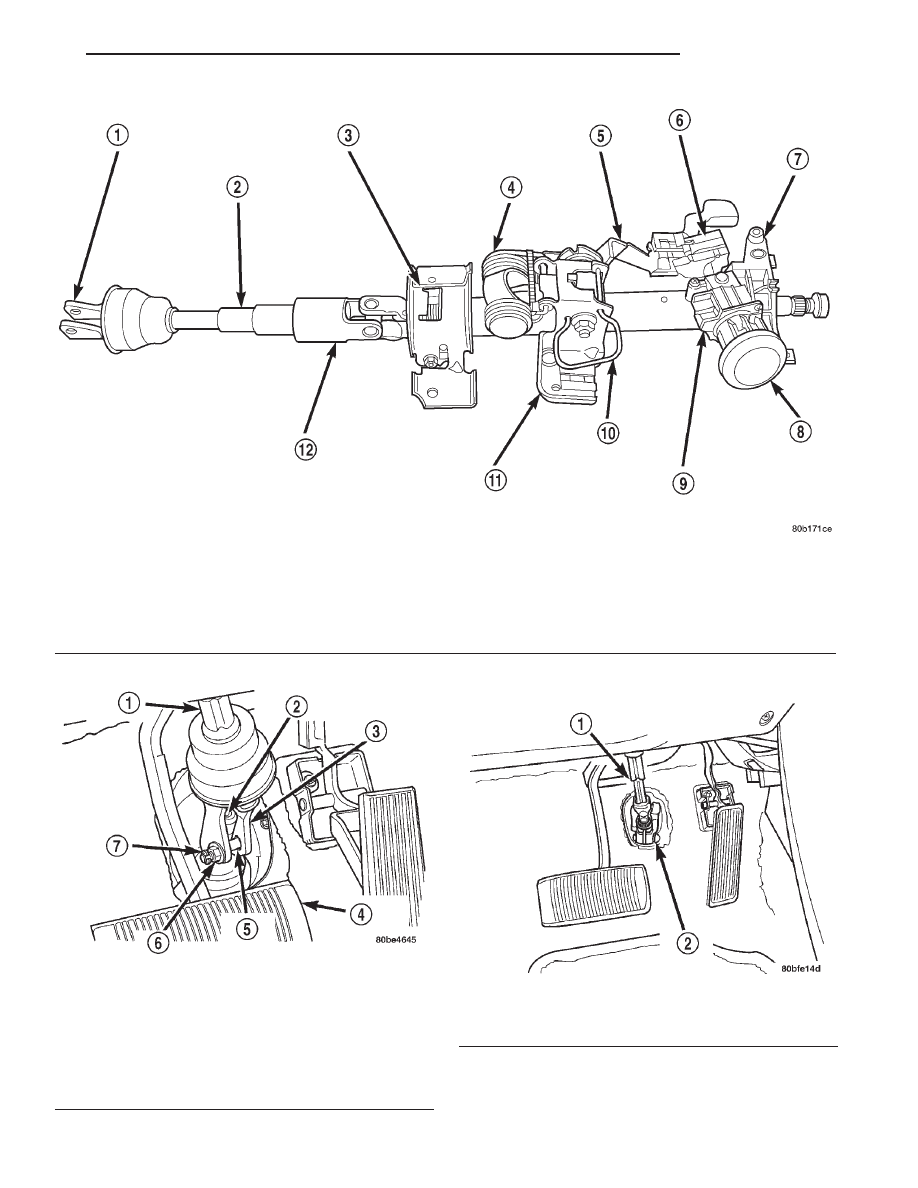
Fig. 1 Steering Column
1 – INTERMEDIATE SHAFT COUPLER
2 – INTERMEDIATE SHAFT
3 – LOWER STEERING COLUMN MOUNTING BRACKET
4 – TILT TORSION SPRING
5 – TILT LEVER
6 – IGNITION SWITCH
7 – SWITCH HOUSING
8 – TRIM RING
9 – LOCK CYLINDER HOUSING
10 – SHIPPING PIN
11 – STEERING COLUMN UPPER MOUNTING BRACKET
12 – INTERMEDIATE SHAFT FLEX JOINT
Fig. 2 Slap Coupler Intermediate Shaft
1 – INTERMEDIATE SHAFT
2 – STEERING GEAR SHAFT
3 – COUPLER
4 – BRAKE PEDAL
5 – PINCH BOLT
6 – NUT
7 – “E” CLIP
Fig. 3 Slider-Stage Intermediate Shaft
1 – INTERMEDIATE SHAFT
2 – PINCH BOLT
JX
STEERING
19 - 49
DESCRIPTION AND OPERATION (Continued)
DIAGNOSIS AND TESTING
STEERING COLUMN
For diagnosis of conditions relating to the steering
column, refer to the STEERING SYSTEM DIAGNO-
SIS CHARTS in DIAGNOSIS AND TESTING in the
POWER STEERING section of this service manual
group.
STEERING COLUMN INTERMEDIATE SHAFT
The steering column intermediate shaft and its
flexible joint couplers (Fig. 1) must be inspected
whenever any of the following conditions exist:
• After the vehicle has been involved in a collision
which deploys the airbag, regardless of the extent of
damage done to the vehicle.
• After the vehicle has been involved in an under-
carriage impact which results in any type of damage
to the front suspension crossmember.
• Under any conditions which result in the steer-
ing column assembly or steering column shaft receiv-
ing a force great enough to move the steering column
or shaft forward of rearward in a vehicle.
Inspect the intermediate shaft and its flexible joint
couplers for any of the following conditions:
• seized or binding bearings
• loose bearing stakes
• bearings not fully seated in the coupler yoke
• bent intermediate shaft
Presence of any of the above faulty conditions call
for replacement of the entire steering column inter-
mediate shaft.
REMOVAL AND INSTALLATION
SERVICE WARNINGS AND CAUTIONS
WARNING: BEFORE
BEGINNING
ANY
SERVICE
PROCEDURES THAT INVOLVES REMOVING THE
AIR BAG. REMOVE AND ISOLATE THE NEGATIVE
(-) BATTERY CABLE (GROUND) FROM THE VEHI-
CLE BATTERY. THIS IS THE ONLY SURE WAY TO
DISABLE THE AIR BAG SYSTEM. FAILURE TO DO
THIS COULD RESULT IN ACCIDENTAL AIR BAG
DEPLOYMENT AND POSSIBLE PERSONAL INJURY.
WARNING: THE AIRBAG SYSTEM IS A SENSITIVE,
COMPLEX ELECTRO-MECHANICAL UNIT. BEFORE
ATTEMPTING TO DIAGNOSE, REMOVE OR INSTALL
THE AIR BAG SYSTEM COMPONENTS YOU MUST
FIRST DISCONNECT AND ISOLATE THE BATTERY
NEGATIVE (GROUND) CABLE. FAILURE TO DO SO
COULD RESULT IN ACCIDENTAL DEPLOYMENT OF
THE AIR BAG AND POSSIBLE PERSONAL INJURY.
THE FASTENERS, SCREWS, AND BOLTS, ORIGI-
NALLY USED FOR THE AIR BAG COMPONENTS,
HAVE SPECIAL COATINGS AND ARE SPECIFI-
CALLY DESIGNED FOR THE AIR BAG SYSTEM.
THEY MUST NEVER BE REPLACED WITH ANY SUB-
STITUTES.
ANYTIME
A
NEW
FASTENER
IS
NEEDED, REPLACE WITH THE CORRECT FASTEN-
ERS PROVIDED IN THE SERVICE PACKAGE OR
FASTENERS
LISTED
IN
THE
PARTS
BOOKS.
BEFORE
SERVICING
A
STEERING
COLUMN
EQUIPPED WITH AN AIR BAG, REFER TO GROUP
8M, ELECTRICAL FOR PROPER AND SAFE SER-
VICE PROCEDURES.
WARNING: SAFETY GOGGLES SHOULD BE WORN
AT ALL TIMES WHEN WORKING ON STEERING
COLUMNS.
CAUTION: Disconnect
negative
(ground)
cable
from the battery, before servicing any column
component.
CAUTION: Do not attempt to remove the pivot pins
to disassemble the tilting mechanism. Damage will
occur.
STEERING COLUMN
WARNING: SAFETY GOGGLES SHOULD BE WORN
AT ALL TIMES WHEN WORKING ON STEERING
COLUMNS.
REMOVAL
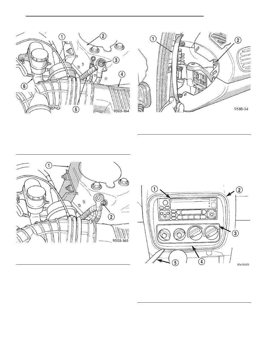
(1) Remove remote ground cable (Fig. 4) from
ground stud on shock tower. Then correctly isolate
ground cable from vehicle by installing isolator on
stud (Fig. 5).
19 - 50
STEERING
JX
(2)
Wait for a minimum of 2 minutes before
starting to remove airbag from steering wheel.
This will allow the airbag system capacitor to
de-energize.
(3) Before beginning removal of steering column
assembly from vehicle, be sure front wheels of vehicle
are in the STRAIGHT AHEAD position.
(4) Remove fuse panel cover from left end of
instrument panel (Fig. 6). Then remove the screw
behind fuse panel cover, attaching the instrument
panel top cover (Fig. 6).
NOTE: When removing the center bezel, only use a
soft tool such as a trim stick (Fig. 7) to pry the cen-
ter bezel from the dash panel. Use of a hard tool
will damage dash panel.
(5) Remove center bezel surrounding radio and cli-
mate control panel from top cover of dash panel
(Fig. 7).
(6) Remove the 3 screws attaching the top cover to
the dash panel (Fig. 8).
(7) Remove the top cover from the dash panel.
Removal of the top cover is required to gain access to
Fig. 4 Remote Ground Cable At Shock Tower
1 – SPEED CONTROL SERVO
2 – LEFT STRUT TOWER
3 – GROUND STUD
4 – AIR CLEANER
5 – REMOTE GROUND CABLE
6 – MASTER CYLINDER
Fig. 5 Correctly Isolated Remote Ground Cable
1 – LEFT STRUT TOWER
2 – GROUND STUD
Fig. 6 Instrument Panel Top Cover Attaching Screw
1 – FUSE PANEL COVER
2 – TOP COVER SCREW
Fig. 7 Center Bezel
1 – RADIO
2 – DASH PANEL
3 – CLIMATE CONTROL PANEL
4 – CENTER BEZEL
5 – TRIM STICK
JX
STEERING
19 - 51
REMOVAL AND INSTALLATION (Continued)
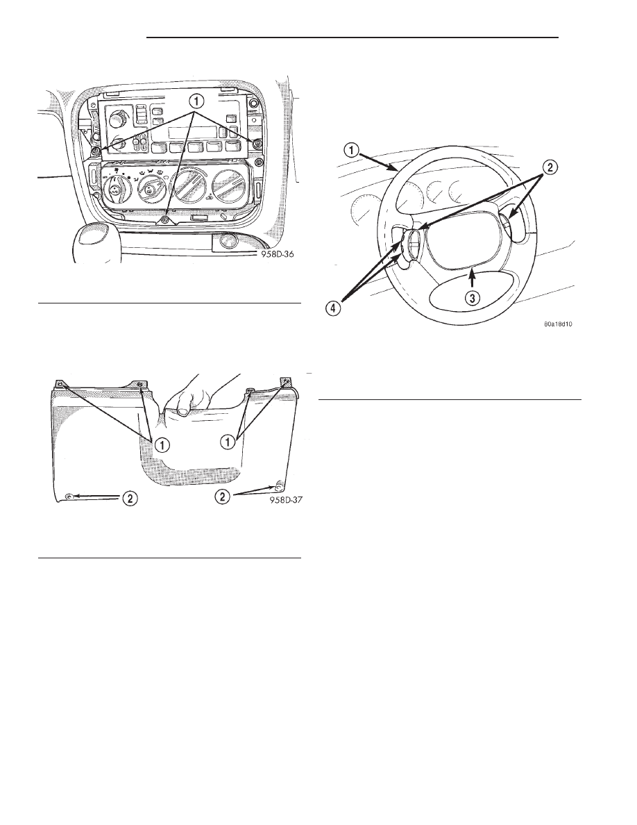
the screws (Fig. 9) attaching the top of the knee bol-
ster to the dash panel.
(8) Remove screws attaching the knee bolster to
the instrument panel (Fig. 9).
WARNING: WHEN
AN
UNDEPLOYED
AIRBAG
ASSEMBLY IS TO BE REMOVED FROM THE STEER-
ING
WHEEL,
DISCONNECT
BATTERY
GROUND
CABLE AND ISOLATE. ALLOW SYSTEM CAPACI-
TOR TO DISCHARGE FOR TWO MINUTES, THEN
BEGIN AIRBAG REMOVAL.
(9) Remove the speed control switches (Fig. 10)
from the steering wheel. The speed control switches
are mounted to the steering wheel using 2 mounting
screws in the side of each speed control switch
(Fig. 10).
(10) Remove both speed control switches from the
wiring harness in the steering wheel.
WARNING: WHEN
HANDLING AN
UNDEPLOYED
AIRBAG MODULE DURING SERVICING OF THE
STEERING COLUMN THE FOLLOWING PRECAU-
TIONS
SHOULD
BE
OBSERVED. AT
NO
TIME
SHOULD ANY SOURCE OF ELECTRICITY BE PER-
MITTED NEAR THE INFLATOR ON THE BACK OF
THE AIRBAG MODULE. WHEN CARRYING A LIVE
MODULE, THE TRIM COVER SHOULD BE POINTED
AWAY FROM THE BODY TO MINIMIZE INJURY IF
MODULE ACCIDENTLY DEPLOYS. IF AIRBAG MOD-
ULE IS PLACED ON A BENCH OR OTHER SUR-
FACE, PLASTIC COVER SHOULD BE FACE UP TO
MINIMIZE MOVEMENT IN CASE OF ACCIDENTAL
DEPLOYMENT.
Fig. 8 Instrument Panel Top Cover Attaching Screws
1 – TOP COVER SCREWS
Fig. 9 Knee Bolster Attaching Screw Locations
1 – KNEE BOLSTER SCREW LOCATIONS UNDER TOP COVER
2 – LOWER SCREW LOCATIONS
Fig. 10 Speed Control Switches
1 – STEERING WHEEL
2 – SPEED CONTROL SWITCHES
3 – AIRBAG
4 – MOUNTING SCREWS
19 - 52
STEERING
JX
REMOVAL AND INSTALLATION (Continued)
Нет комментариевНе стесняйтесь поделиться с нами вашим ценным мнением.
Текст