
Chrysler Stratus Convertible. Manual — part 263
LAMP SYSTEMS
TABLE OF CONTENTS
page
page
DESCRIPTION AND OPERATION
DIAGNOSIS AND TESTING
LAMP SYSTEM DIAGNOSTIC PROCEDURES . . . 18
ILLUMINATED ENTRY DIAGNOSTIC
PROCEDURES . . . . . . . . . . . . . . . . . . . . . . . . . 18
DESCRIPTION AND OPERATION
DAYTIME RUNNING LAMP (CANADA)
DESCRIPTION
JX vehicles built for use in Canada are equipped
with a Daytime Running Lamp (DRL) system. The
DRL system operates the headlamps at 50% illumi-
nation with the headlamp switch OFF, park brake
released and the ignition ON. The DRL system is
controlled by the Daytime Running Lamp Module
located on the back of the multi-function module
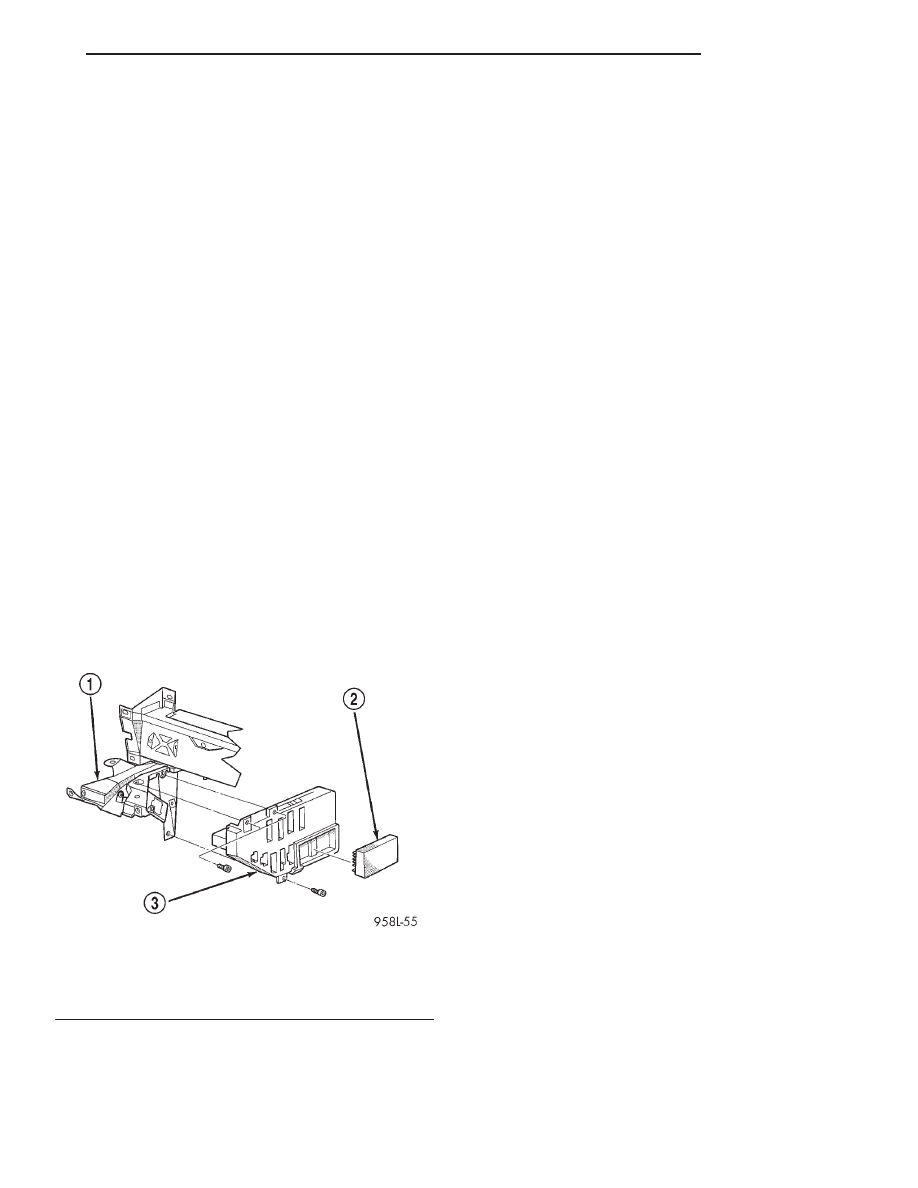
behind the instrument panel (Fig. 1). The DRL mod-
ule overrides the headlamp switch when the head-
lamps are turned OFF. The headlamps operate
normally when the headlamps are turned ON. Refer
to Group 8W, Wiring Diagrams, for component loca-
tions and circuit information.
HEADLAMP TIME DELAY SYSTEM
DESCRIPTION
The optional Headlamp Time Delay system is con-
trolled by the Body Controller (BC) and a relay
located in the junction block. The headlamp time
delay system can be activated by turning ON the
headlamps when the engine is running, turn OFF
the ignition switch, then turn OFF the headlamp
switch. The BC will allow the headlamps to remain
ON for 90 seconds before they automatically turn off.
Refer to the Owner’s Manual for more information.
ILLUMINATED ENTRY
DESCRIPTION
The Illuminated Entry System is available on vehi-
cles equipped with the Remote Keyless Entry system.
The Illuminated Entry System turns ON the courtesy
lamps when the remote keyless entry system is acti-
vated. The Remote Keyless Entry Module and the
Body Controller are used to control the system. Cour-
tesy lamps will turn on for 30 seconds (
61 second)
and fade to OFF over a five second period.
The Illuminated Entry System also turns ON the
courtesy lamps (and ignition switch lamp) when door
is opened. The courtesy lamps will remain ON while
the door is open, then fade to OFF 30 seconds (
61
second) after the last door is closed.
The courtesy and ignition switch lamps will fade to
OFF immediately when the ignition is switched to
ON.
The Illuminated Entry System cannot be activated
during the 30 second (
61 second) period after the
ignition switch is turned OFF. After a door is opened
and closed during this 30 second period, the system
will function as previously described.
When the battery voltage has been interrupted to
the Illuminated Entry System, the system will not
function until the remote keyless entry UNLOCK is
actuated.
Fig. 1 Daytime Running Lamp Module
1 – FUSE BLOCK BRACKET
2 – DAYTIME RUNNING LAMP MODULE
3 – MULTI FUNCTION MODULE
JX
LAMPS
8L - 17
DIAGNOSIS AND TESTING
LAMP SYSTEM DIAGNOSTIC PROCEDURES
Refer to Group 8W, Wiring Diagrams for compo-
nent location and circuit information. Refer to the
Body Systems Diagnostic Procedures Manual for
more information.
ILLUMINATED ENTRY DIAGNOSTIC
PROCEDURES
When testing the system, all doors must be closed
to prevent courtesy lamps from lighting. Verify that
remote keyless entry system is operating properly
before testing illuminated entry circuits. The body
controller uses input from the remote keyless entry
system to switch ON the courtesy lamps.
Refer to Group 8W, Wiring Diagrams for compo-
nent location and circuit information. Refer to Body
Systems Diagnostic Procedures Manual for more
information.
8L - 18
LAMPS
JX
BULB APPLICATION
TABLE OF CONTENTS
page
page
SPECIFICATIONS
EXTERIOR LAMPS. . . . . . . . . . . . . . . . . . . . . . . . 19
INTERIOR LAMPS . . . . . . . . . . . . . . . . . . . . . . . . 19
SPECIFICATIONS
EXTERIOR LAMPS
CAUTION: Do not use bulbs that have a higher can-
dle power than the bulb listed in the Bulb Applica-
tion Table. Damage to lamp can result.
CAUTION: Do not touch halogen bulbs with fingers
or other oily surfaces. Bulb life will be reduced.
Headlamp . . . . . . . . . . . . . . . . . . . 9007QL or 9007
Fog lamp . . . . . . . . . . . . . . . . . . . . . . . . . . . . . 9006
Park/Turn Signal . . . . . . . . . . . . . . . 3157K or 3157
Center High Mounted Stop . . . . . . . . . 921 (W16W)
Tail/Brake/Turn Signal . . . . . . . . . 3457K (3357LL)
Back up . . . . . . . . . . . . . . . . . . . . . . . . 921 (W16W)
Side Marker . . . . . . . . . . . . . . . . . . . . . . . . . . . 168
License Plate . . . . . . . . . . . . . . . . . . . . . . . . . . . 168
INTERIOR LAMPS
CAUTION: Do not use bulbs that have a higher can-
dle power than the bulb listed in the Bulb Applica-
tion Table. Damage to lamp can result.
CAUTION: Do not touch halogen bulbs with fingers
or other oily surfaces. Bulb life will be reduced.
DIMMER CONTROLLED LAMPS
Service procedures for most of the lamps in the
instrument panel, instrument cluster and switches
are located in Group 8E, Instrument Panel and
Gauges. Some components have lamps that can only
be serviced by a Authorized Service Center (ASC)
after the component is removed from the vehicle.
Contact local dealer for location of nearest ASC.
A/C Heater Control . . . . . . . . . . . . . . . . . . . . . . . 37
A/C Heater ISO Symbols . . . . . . . . . . . . . . . . . LED
Ash Receiver . . . . . . . . . . . . . . . . . . . . . . . . . . . . 37
Instrument Cluster . . . . . . . . . . . . . . . . . . . PC194
Radio . . . . . . . . . . . . . . . . . . . . . . . . . . . . . . . . ASC
INDICATOR LAMPS
Service procedures for most of the lamps in the
instrument panel, instrument cluster and switches
are located in Group 8E, Instrument Panel and
Gauges.
A/C Compressor . . . . . . . . . . . . . . . . . . . . . . . . LED
Air Bag . . . . . . . . . . . . . . . . . . . . . . . . . . . . . PC194
Anti-lock Brake . . . . . . . . . . . . . . . . . . . . . . PC194
Brake Warning . . . . . . . . . . . . . . . . . . . . . . . PC194
Check Engine . . . . . . . . . . . . . . . . . . . . . . . . PC194
Console Shift Indicator . . . . . . . . . . . . . . . . . . LED
Engine Oil Pressure . . . . . . . . . . . . . . . . . . . PC194
Engine Temperature . . . . . . . . . . . . . . . . . . . PC194
Fog Lamp . . . . . . . . . . . . . . . . . . . . . . . . . . . PC161
Generator . . . . . . . . . . . . . . . . . . . . . . . . . . . PC194
High Beam . . . . . . . . . . . . . . . . . . . . . . . . . . PC194
Low Fuel . . . . . . . . . . . . . . . . . . . . . . . . . . . PC194
Rear Window Defogger . . . . . . . . . . . . . . . . . . LED
Seat Belt . . . . . . . . . . . . . . . . . . . . . . . . . . . PC194
Security Alarm . . . . . . . . . . . . . . . . . . . . . . . . LED
Shift Indicator . . . . . . . . . . . . . . . . . . . . VF Display
Speed Control . . . . . . . . . . . . . . . . . . . . . . . . PC194
Turn Signal . . . . . . . . . . . . . . . . . . . . . . . . . PC194
NON-DIMMING LAMPS
Service procedures for most of the lamps in the fol-
lowing list can be found in Group 8L, Lamps. Some
components have lamps that can only be serviced by
a Authorized Service Center (ASC) after the compo-
nent is removed from the vehicle. Contact local
dealer for location of nearest ASC.
Door Courtesy Lamp . . . . . . . . . . . . . . . . . . . . . 168
Floor Console Courtesy Lamp . . . . . . . . . . . . . . 906
Glove Box Lamp . . . . . . . . . . . . . . . . . . . . . . . . 194
Ignition Lock . . . . . . . . . . . . . . . . . . . . . . . 4856321
Map Lamp . . . . . . . . . . . . . . . . . . . . . . . . . . . 212–2
Trunk . . . . . . . . . . . . . . . . . . . . . . . . . . . . . . . . 912
Visor Vanity . . . . . . . . . . . . . . . . . . . . . . . . 6501966
JX
LAMPS
8L - 19
Нет комментариевНе стесняйтесь поделиться с нами вашим ценным мнением.
Текст