
Chrysler Stratus Convertible. Manual — part 5

SPECIFICATIONS
TORQUE
DESCRIPTION
N·m
Ft.
Lbs.
In.
Lbs.
Band Clamps—Fastener
75
55
—
Catalytic Converter to Exhaust
Manifold Flange—Fasteners
32
24
—
Cross Under Pipe—Fasteners
31
—
250
Heat Shields to Body—
Fasteners
5
—
40
JX
EXHAUST SYSTEM
11 - 7
EXHAUST SYSTEM
TABLE OF CONTENTS
page
page
DESCRIPTION AND OPERATION
EXHAUST SYSTEM. . . . . . . . . . . . . . . . . . . . . . . . 1
CATALYTIC CONVERTER. . . . . . . . . . . . . . . . . . . . 1
HEAT SHIELDS . . . . . . . . . . . . . . . . . . . . . . . . . . . 2
EXHAUST FLEX-JOINT COUPLING. . . . . . . . . . . . 3
DIAGNOSIS AND TESTING
EXHAUST SYSTEM. . . . . . . . . . . . . . . . . . . . . . . . 3
REMOVAL AND INSTALLATION
EXHAUST SYSTEM. . . . . . . . . . . . . . . . . . . . . . . . 4
CLEANING AND INSPECTION
EXHAUST SYSTEM. . . . . . . . . . . . . . . . . . . . . . . . 6
ADJUSTMENTS
ALIGNMENT . . . . . . . . . . . . . . . . . . . . . . . . . . . . . 6
SPECIFICATIONS
TORQUE . . . . . . . . . . . . . . . . . . . . . . . . . . . . . . . . 7
DESCRIPTION AND OPERATION
EXHAUST SYSTEM
DESCRIPTION
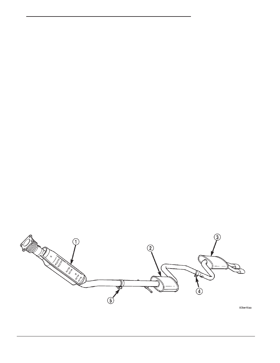
The exhaust system is produced in one configura-
tion (Fig. 1). The system has a front mounted cata-
lytic converter, muffler and resonator. Tail pipes,
mufflers, and resonators are tuned to each power-
train combination.
CATALYTIC CONVERTER
DESCRIPTION
The under-floor, three-way catalytic converter inlet
is connected to the exhaust manifold by use of a flex
joint and gasket. The outlet connects to the exhaust
system.
OPERATION
The three-way catalytic converter simultaneously
converts three exhaust emissions into harmless
gases. Specifically, HC and CO emissions are con-
verted into water (H2O) and carbon dioxide (CO2).
Oxides of Nitrogen (NOx) are converted into elemen-
tal Nitrogen (N) and water. The three-way catalyst is
most efficient in converting HC, CO and NOx at the
stoichiometric air fuel ratio of 14.7:1.
The oxygen content in a catalyst is important for
efficient conversion of exhaust gases. When a high
oxygen content (lean) air/fuel ratio is present for an
extended period, oxygen content in a catalyst can
Fig. 1 Exhaust System
1 – CATALYTIC CONVERTER
2 – RESONATOR
3 – MUFFLER
4 – CLAMP
5 – CLAMP
JX
EXHAUST SYSTEM
11 - 1
reach a maximum. When a rich air/fuel ratio is
present for an extended period, the oxygen content in
the catalyst can become totally depleted. When this
occurs, the catalyst fails to convert the gases. This is
known as catalyst “punch through.
9
Catalyst operation is dependent on its ability to
store and release the oxygen needed to complete the
emissions-reducing chemical reactions. As a catalyst
deteriorates, its ability to store oxygen is reduced.
Since the catalyst’s ability to store oxygen is some-
what related to proper operation, oxygen storage can
be used as an indicator of catalyst performance.
Refer to the appropriate Powertrain Diagnostic Pro-
cedure for diagnosis of a catalyst related Diagnostic
Trouble Code (DTC).
The combustion reaction caused by the catalyst
releases additional heat in the exhaust system, caus-
ing temperature increases in the area of the reactor
under severe operating conditions. Such conditions
can exist when the engine misfires or otherwise does
not operate at peak efficiency. Do not remove spark
plug wires from plugs or by any other means short
out cylinders, if exhaust system is equipped with a
catalytic converter. Failure of the catalytic converter
can occur due to temperature increases caused by
unburned fuel passing through the converter. This
deterioration of the catalyst core can result in exces-
sively high emission levels, noise complaints, and
exhaust restrictions.
The use of catalysts also involves some non-auto-
motive problems. Unleaded gasoline must be used to
avoid poisoning the catalyst core. Do not allow engine
to operate above 1200 RPM in neutral for extended
periods over 5 minutes. This condition may result in
excessive exhaust system/floor pan temperatures
because of no air movement under the vehicle.
CAUTION: Due to exterior physical similarities of
some catalytic converters with pipe assemblies,
extreme care should be taken with replacement
parts.
There
are
internal
converter
differences
required in some parts of the country (particularly
vehicles
built
for
States
with
strict
emission
requirements).
HEAT SHIELDS
DESCRIPTION
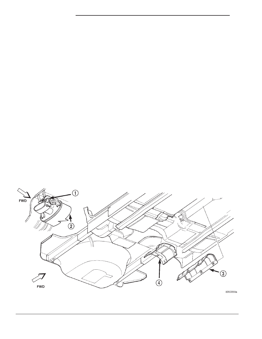
The exhaust system heat shields are attached to
the under body of the vehicle (Fig. 2). All engines are
equipped with a heat shield crimped on the top of the
catalytic converter.
OPERATION
Heat shields are needed to protect both the vehicle
and the environment from the high temperatures
developed near the catalytic converter. All engines
Fig. 2 Heat Shields
1 – GROUND STRAP
2 – MUFFLER
3 – HEAT SHIELD
4 – RESONATOR HEAT SHIELD
11 - 2
EXHAUST SYSTEM
JX
DESCRIPTION AND OPERATION (Continued)
Нет комментариевНе стесняйтесь поделиться с нами вашим ценным мнением.
Текст