
Chrysler Stratus Convertible. Manual — part 210
(5) Install the wheel and tire assembly on vehicle.
(6) Road test vehicle to ensure proper operation of
the base and ABS systems.
WHEEL SPEED SENSOR (REAR)
This procedure is for the removal and installation
of one of the two rear wheel speed sensors.
REMOVAL
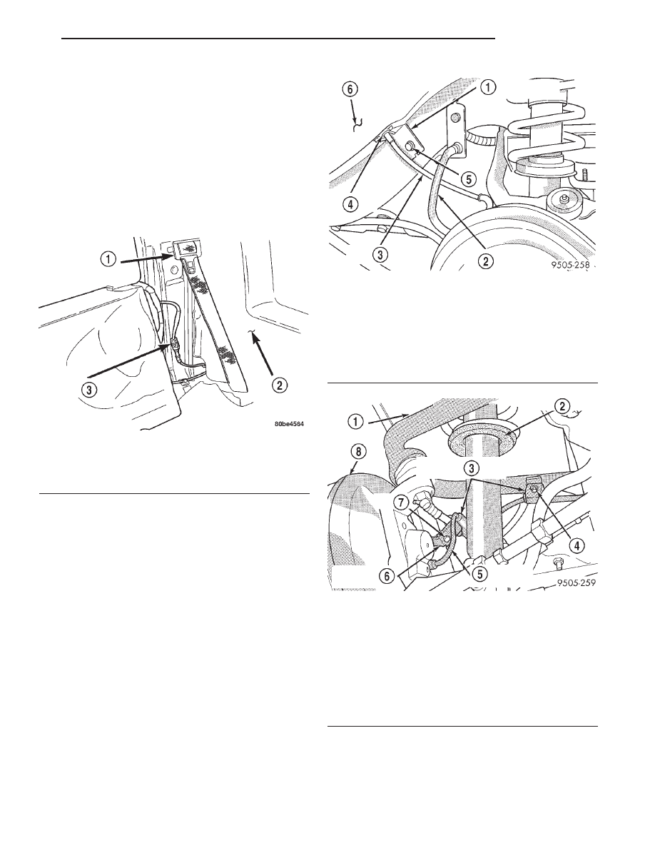
(1) Remove the rear seat cushion and back, then
disconnect the wheel speed sensor cable connector
from the vehicle wiring harness (Fig. 46).
(2) Raise vehicle on jack stands or centered on a
frame contact type hoist. See Hoisting in the Lubri-
cation and Maintenance section of this manual, for
the required lifting procedure to be used for this
vehicle.
(3) Remove the rear tire and wheel assembly from
the vehicle.
(4) Remove speed sensor cable sealing grommet
retainer (Fig. 47) from the rear frame rail of the
vehicle. Then remove speed sensor cable sealing
grommet and cable from hole in body of vehicle.
(5) Remove speed sensor routing clips from the
rear upper control arm and brake flex hose routing
bracket (Fig. 48).
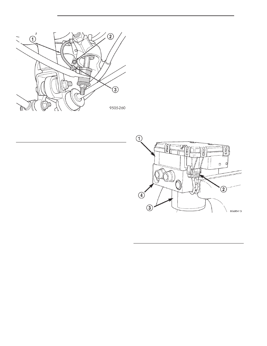
(6) Remove the rear speed sensor from the rear
brake support plate (Fig. 49).
Fig. 46 Connection At Vehicle Wiring Harness
1 – OUTER SEAT BELT
2 – QUARTER TRIM PANEL
3 – CONNECTOR
Fig. 47 Rear Speed Senor Cable Attachment To
Body
1 – SEALING GROMMET RETAINER
2 – BRAKE FLEX HOSE
3 – SPEED SENSOR CABLE
4 – SEALING GROMMET
5 – BOLT
6 – REAR INNER FENDER
Fig. 48 Speed Sensor Cable Attachment To Rear
Suspension
1 – UPPER CONTROL ARM
2 – SHOCK ABSORBER
3 – SPEED SENSOR CABLE ROUTING CLIPS
4 – BOLT
5 – SPEED SENSOR CABLE
6 – BRAKE FLEX HOSE BRACKET
7 – BOLT
8 – BRAKE DRUM
JX
BRAKES
5 - 103
REMOVAL AND INSTALLATION (Continued)
INSTALLATION
CAUTION: Proper installation of wheel speed sen-
sor cables is critical to continued system operation.
Be sure that cables are installed in retainers. Fail-
ure to install cables in retainers as shown in this
section may result in contact with moving parts
and/or over extension of cables, resulting in an
open circuit.
(1) Install speed sensor head into brake support
plate (Fig. 49).
(2) Install wheel speed sensor attaching bolt (Fig.
49). Tighten the speed sensor head attaching bolt to
8 N·m (75 in. lbs.)
(3) Install speed sensor cable routing clips (Fig.
48) on the brake flex hose bracket and the bracket on
the upper control arm. Install and securely tighten
the routing clip attaching bolts.
(4) Install connector end of speed sensor cable
through hole in inner fender and into trunk of vehi-
cle.
(5) Install speed control sealing grommet into hole
in inner fender. Install the sealing grommet retainer
and attaching bolt (Fig. 47) on rear frame rail.
Securely tighten retainer attaching bolt.
(6) Install the tire and wheel assembly on vehicle.
(7) Lower vehicle.
(8) Reconnect the wheel speed sensor cable connec-
tor to the vehicle wiring harness (Fig. 46), install any
removed foam tape back around connectors, then
reinstall the rear seat back and cushion.
(9) Road test vehicle to ensure proper operation of
the base and ABS systems.
DISASSEMBLY AND ASSEMBLY
INTEGRATED CONTROL UNIT
REMOVAL
NOTE: To replace the hydraulic control unit (HCU)
or the controller antilock brake (CAB) on this vehi-
cle, the entire integrated control unit (ICU) needs to
be removed from the vehicle. The CAB can then be
separated from the HCU. Do not attempt to replace
the CAB with the ICU mounted in the vehicle.
(1) Remove the ICU from the vehicle. Refer INTE-
GRATED CONTROL UNIT in the REMOVAL AND
INSTALLATION section in this section of the service
manual.
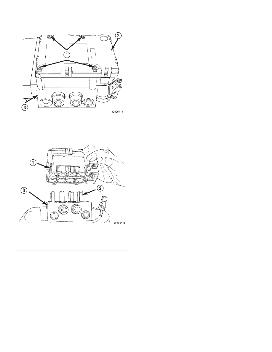
(2) Disconnect the pump/motor wiring harness
(Fig. 50) from the CAB.
(3) Remove the 4 bolts (Fig. 51) attaching the CAB
to the HCU.
(4) Remove the CAB from the HCU (Fig. 52).
INSTALLATION
(1) Install the CAB (Fig. 52) on the HCU.
(2) Install the 4 bolts mounting the CAB (Fig. 51)
to the HCU. Tighten the CAB mounting bolts to a
torque of 2 N·m (17 in. lbs.).
(3) Plug the pump/motor wiring harness into the
CAB (Fig. 50).
(4) Install the ICU in the vehicle.
(5) Bleed the base and ABS hydraulic systems.
Refer to ANTILOCK BRAKE SYSTEM BLEEDING
in this section of this service manual group.
Fig. 49 Rear Speed Sensor Head Attachment To
Brake Support Plate
1 – SPEED SENSOR CABLE
2 – BOLT
3 – SPEED SENSOR HEAD
Fig. 50 Pump/Motor To CAB Wiring Harness
1 – CAB
2 – PUMP MOTOR WIRING HARNESS
3 – PUMP MOTOR
4 – HCU VALVE BLOCK
5 - 104
BRAKES
JX
REMOVAL AND INSTALLATION (Continued)
(6) Road test the vehicle to ensure proper opera-
tion of the base brakes and ABS.
SPECIFICATIONS
TONE WHEEL RUNOUT
FRONT TONE WHEEL:
Maximum Runout . . . . . . . . . 0.25 mm (0.009 in.)
REAR TONE WHEEL:
Maximum Runout . . . . . . . . . 0.25 mm (0.009 in.)
WHEEL SPEED SENSOR-TO-TONE WHEEL
CLEARANCE
FRONT WHEEL:
Minimum Clearance . . . . . . . 0.17 mm (0.007 in.)
Maximum Clearance . . . . . . . 1.80 mm (0.072 in.)
REAR WHEEL:
Minimum Clearance . . . . . . . 0.37 mm (0.015 in.)
Maximum Clearance . . . . . . . 1.50 mm (0.059 in.)
WHEEL SPEED SENSOR RESISTANCE
ALL:
Allowable Resistance . . . . . . . . 2160 - 2640 ohms
BRAKE FASTENER TORQUE SPECIFICATIONS
DESCRIPTION
TORQUE
MASTER CYLINDER:
To Vacuum Booster Mounting Nut . . . . . . . 28 N·m
(250 in. lbs.)
BRAKE BOOSTER:
To Dash Panel Mounting Nuts . . . . . . . . . . 28 N·m
(250 in. lbs.)
BRAKE TUBES:
Tube Nuts . . . . . . . . . . . . . . . . 17 N·m (145 in. lbs.)
BRAKE HOSE:
Caliper Banjo Bolt . . . . . . . . . . . 48 N·m (35 ft. lbs.)
Intermediate Bracket . . . . . . . . 23 N·m (17 ft. lbs.)
DISC BRAKE CALIPER:
Guide Pin Bolts . . . . . . . . . . . 22 N·m (192 in. lbs.)
Bleeder Screw . . . . . . . . . . . . . . 20 N·m (15 ft. lbs.)
REAR WHEEL CYLINDER:
To Support Plate Mounting Bolts . . . . . . . . 11 N·m
(97 in. lbs.)
Bleeder Screw . . . . . . . . . . . . . . 8 N·m (75 in. lbs.)
BRAKE SUPPORT PLATE:
To Axle Mounting Bolts . . . . . . . 63 N·m (46 ft. lbs.)
INTEGRATED CONTROL UNIT (HCU AND
CAB):
To Mounting Bracket Bolts . . . . 11 N·m (97 in. lbs.)
Bracket To Crossmember Mounting Bolts . . . . 28 N·m
(250 in. lbs.)
CAB To HCU Mounting Bolts . . . 2 N·m (17 in. lbs.)
PARKING BRAKE:
Lever Mounting Nuts . . . . . . . 28 N·m (250 in. lbs.)
REAR HUB AND BEARING:
To Knuckle Retaining Nut . . . 250 N·m (185 ft. lbs.)
Stud Lug Nut . . . . . . 109–150 N·m (80–110 ft. lbs.)
Fig. 51 CAB Attaching Bolts
1 – MOUNTING BOLTS
2 – CAB
3 – HCU VALVE BLOCK
Fig. 52 Remove/Install CAB
1 – CAB
2 – HCU VALVES
3 – HCU VALVE BLOCK
JX
BRAKES
5 - 105
DISASSEMBLY AND ASSEMBLY (Continued)
Нет комментариевНе стесняйтесь поделиться с нами вашим ценным мнением.
Текст