
Chrysler Stratus Convertible. Manual — part 213

OIL CONTAMINATION
Oil contamination indicates a leak at the rear main
seal and/or transaxle input shaft. Oil leaks produce a
residue of oil on the transaxle housing interior, clutch
cover and flywheel. Heat buildup caused by slippage
can bake the oil residue onto the components. This
glaze-like residue ranges in color from amber to
black.
GREASE CONTAMINATION
Grease contamination is usually a product of over-
lubrication. During clutch service, apply only a small
amount of grease to the input shaft splines. Excess
grease may be thrown off during operation, contami-
nating the disc.
ROAD SPLASH/WATER CONTAMINATION
Road splash contamination is usually caused by
driving the vehicle through deep water puddles.
Water can be forced into the clutch housing, causing
clutch components to become contaminated. Facing of
disc will absorb moisture and bond to the flywheel
and/or, pressure plate, if vehicle is allowed to stand
for some time before use. If this condition occurs,
replacement of clutch assembly may be required.
Drive the vehicle until normal clutch operating tem-
perature has been obtained. This will dry off disc
assembly, pressure plate, and flywheel.
CLEANING PRECAUTIONS
Condensation from steam vapors tend to accumu-
late on the internal clutch mechanism when the vehi-
cle is steam cleaned. Facing of disc will absorb
moisture and will bond to flywheel and/or pressure
plate, if vehicle is allowed to stand for some time
before use. If this condition occurs, it may require
replacement of clutch assembly. After cleaning, drive
the vehicle to its normal clutch operating tempera-
ture. This will dry off disc assembly, pressure plate,
and flywheel.
ADJUSTMENTS
CLUTCH CABLE
The manual transaxle clutch release system has a
unique self-adjusting mechanism to compensate for
clutch disc wear (Fig. 9). This adjuster mechanism is
located within the clutch cable assembly. The preload
spring maintains tension on the cable. This tension
keeps the clutch release bearing continuously loaded
against the fingers of the clutch cover assembly.
ADJUSTER MECHANISM FUNCTION CHECK
(1) With slight pressure, pull the clutch release
lever end of the cable to draw the cable taut. Push
the clutch cable housing toward the dash panel. With
less than 25 lbs. of effort the cable housing should
move 30-50mm. This indicates proper adjuster mech-
anism function. If the cable does not adjust, deter-
mine if the mechanism is properly seated on the
bracket.
(2) If the adjust mechanism functions properly,
guide the cable through the slot in the transaxle
housing. Connect cable to release lever, seating the
cupped washer securely on lever tangs.
(3) Pull back on clutch cable housing and insert
into transaxle housing (Fig. 10).
Fig. 9 Clutch Cable Routing
1 – CLUTCH CABLE AT CLUTCH PEDAL
2 – CLUTCH CABLE AT TRANSAXLE
Fig. 10 Cable at Transaxle
1 – BELLHOUSING
2 – CLUTCH CABLE
JX
CLUTCH
6 - 9
CLEANING AND INSPECTION (Continued)
(4) Reinstall cable inspection cover and air cleaner
assembly. Check clutch pedal position switch opera-
tion.
CLUTCH PEDAL POSITION SWITCH
The clutch pedal position switch is mounted to a
bracket located behind the clutch pedal. The switch
is held in place by four plastic wing tabs.
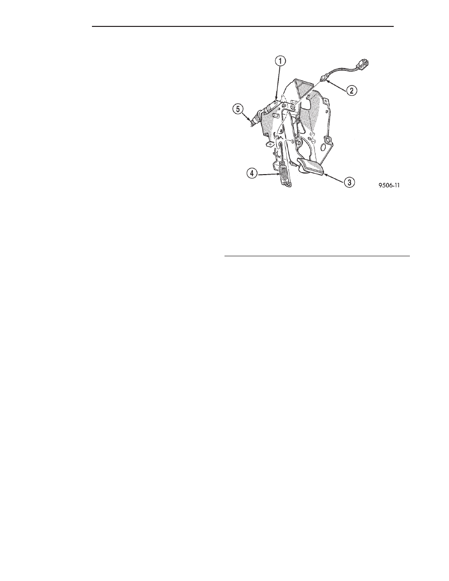
The clutch pedal position switch IS NOT adjust-
able. The pedal blade contacts the switch in the down
position (Fig. 11).
SPECIFICATIONS
NV T350 (A-578) CLUTCH TIGHTENING
REFERENCE
DESCRIPTION
TORQUE
Drive Plate To Clutch Bolts . . . . 75 N·m (55 ft. lbs.)
Drive Plate To Crankshaft Bolts . . . . . . . . . 95 N·m
(70 ft. lbs.)
Clutch Pedal Pivot Shaft Nut . . 41 N·m (30 ft. lbs.)
Fig. 11 Clutch Pedal Position Switch and
Components
1 – UPSTOP/SPACER
2 – CLUTCH PEDAL POSITION SWITCH
3 – CLUTCH PEDAL
4 – CLUTCH PEDAL RETURN SPRING
5 – CLUTCH CABLE
6 - 10
CLUTCH
JX
ADJUSTMENTS (Continued)
COOLING SYSTEM
TABLE OF CONTENTS
page
page
DESCRIPTION AND OPERATION
COOLING SYSTEM . . . . . . . . . . . . . . . . . . . . . . . . 2
COOLANT . . . . . . . . . . . . . . . . . . . . . . . . . . . . . . . 2
ENGINE THERMOSTAT—2.5L ENGINE . . . . . . . . 3
COOLANT RECOVERY SYSTEM . . . . . . . . . . . . . . 3
HOSE CLAMPS . . . . . . . . . . . . . . . . . . . . . . . . . . . 4
ENGINE BLOCK HEATER . . . . . . . . . . . . . . . . . . . 5
RADIATOR . . . . . . . . . . . . . . . . . . . . . . . . . . . . . . 5
COOLING SYSTEM FAN . . . . . . . . . . . . . . . . . . . . 5
COOLING SYSTEM PRESSURE CAP . . . . . . . . . . 6
ACCESSORY DRIVE BELTS . . . . . . . . . . . . . . . . . 6
TRANSMISSION OIL COOLER . . . . . . . . . . . . . . . 6
TRANSMISSION OIL COOLER EXTERNAL . . . . . . 7
DIAGNOSIS AND TESTING
COOLING SYSTEM DIAGNOSIS . . . . . . . . . . . . . . 8
ENGINE THERMOSTAT TESTING . . . . . . . . . . . . 14
WATER PUMP DIAGNOSIS . . . . . . . . . . . . . . . . 14
COOLING SYSTEM FLOW CHECK . . . . . . . . . . . 14
RADIATOR FAN CONTROL . . . . . . . . . . . . . . . . . 15
ELECTRIC FAN MOTOR TEST. . . . . . . . . . . . . . . 15
COOLANT CONCENTRATION TESTING. . . . . . . . 15
COOLING SYSTEM LEAK TESTING . . . . . . . . . . 16
COOLING SYSTEM PRESSURE RELIEF
CHECK . . . . . . . . . . . . . . . . . . . . . . . . . . . . . . . 16
TESTING . . . . . . . . . . . . . . . . . . . . . . . . . . . . . 17
LOW COOLANT LEVEL AERATION . . . . . . . . . . . 17
COOLING SYSTEM DEAERATION. . . . . . . . . . . . 17
ACCESSORY DRIVE BELT. . . . . . . . . . . . . . . . . . 17
ENGINE BLOCK HEATER . . . . . . . . . . . . . . . . . . 18
SERVICE PROCEDURES
COOLANT LEVEL CHECK—ROUTINE. . . . . . . . . 18
COOLANT—ADDING ADDITIONAL. . . . . . . . . . . 18
COOLANT LEVEL SERVICING—2.5L ENGINE . . 18
COOLING SYSTEM—DRAINING. . . . . . . . . . . . . 18
COOLING SYSTEM—REFILLING . . . . . . . . . . . . 19
REMOVAL AND INSTALLATION
WATER PUMP—2.5L ENGINE . . . . . . . . . . . . . . 19
THERMOSTAT—2.5L ENGINE . . . . . . . . . . . . . . 20
RADIATOR . . . . . . . . . . . . . . . . . . . . . . . . . . . . . 20
RADIATOR DRAINCOCK . . . . . . . . . . . . . . . . . . . 22
RADIATOR FAN, MOTOR AND SHROUD . . . . . . 22
COOLANT RECOVERY BOTTLE . . . . . . . . . . . . . 23
ENGINE BLOCK HEATER . . . . . . . . . . . . . . . . . . 23
ACCESSORY DRIVE BELTS . . . . . . . . . . . . . . . . 24
CLEANING AND INSPECTION
WATER PUMP—2.5L ENGINE . . . . . . . . . . . . . . 26
ACCESSORY DRIVE BELT. . . . . . . . . . . . . . . . . . 26
COOLING SYSTEM PRESSURE CAP . . . . . . . . . 26
RADIATOR . . . . . . . . . . . . . . . . . . . . . . . . . . . . . 27
COOLING SYSTEM CLEANING/FLUSHING . . . . . 27
TRANSMISSION OIL COOLER . . . . . . . . . . . . . . 27
ADJUSTMENTS
BELT TENSION GAUGE METHOD . . . . . . . . . . . . 27
SPECIFICATIONS
SPECIAL TOOLS
COOLING SYSTEM . . . . . . . . . . . . . . . . . . . . . . . 28
JX
COOLING SYSTEM
7 - 1
DESCRIPTION AND OPERATION
COOLING SYSTEM
DESCRIPTION
The cooling system consists of an engine cooling
module, thermostat, coolant, a water pump to circu-
late the coolant. The engine cooling module may con-
sist of a radiator, electric fan motor, shroud, radiator
pressure cap, coolant reserve system, transmission
oil cooler and lines, hoses, clamps, and air condition-
ing condenser.
OPERATION
The primary purpose of a cooling system is to
maintain engine temperature in a range that will
provide satisfactory engine performance and emission
levels under all expected driving conditions. It also
provides hot water (coolant) for heater performance
and cooling for automatic transmission oil. It does
this by transferring heat from engine metal to cool-
ant, moving this heated coolant to the radiator, and
then transferring this heat to the ambient air.
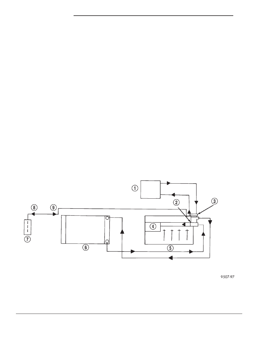
The coolant flow circuits for the 2.5L engine is
shown in (Fig. 1).
COOLANT
DESCRIPTION
ETHYLENE-GLYCOL MIXTURES
CAUTION: Richer antifreeze mixtures cannot be
measured with normal field equipment and can
cause problems associated with 100 percent ethyl-
ene-glycol.
The required ethylene-glycol (antifreeze) and water
mixture depends upon the climate and vehicle oper-
ating conditions. The recommended mixture of 50/50
ethylene-glycol and water will provide protection
against freezing to -37 deg. C (-35 deg. F). The anti-
freeze concentration must always be a minimum of
44 percent, year-round in all climates. If percentage
is lower than 44 percent, engine parts may be
eroded by cavitation, and cooling system com-
ponents may be severely damaged by corrosion.
Maximum protection against freezing is provided
with a 68 percent antifreeze concentration, which
prevents freezing down to -67.7 deg. C (-90 deg. F). A
higher percentage will freeze at a warmer tempera-
ture. Also, a higher percentage of antifreeze can
cause the engine to overheat because the specific
heat of antifreeze is lower than that of water.
Fig. 1 Cooling System Operation—2.5L Engine
1 – HEATER
2 – THERMOSTAT HOUSING
3 – PRESSURE CAP
4 – WATER PUMP
5 – ENGINE
6 – RADIATOR
7 – COOLANT RECOVERY SYSTEM TANK
8 – HEAT UP
9 – COOL DOWN
7 - 2
COOLING SYSTEM
JX
Нет комментариевНе стесняйтесь поделиться с нами вашим ценным мнением.
Текст