
Chrysler Stratus Convertible. Manual — part 268
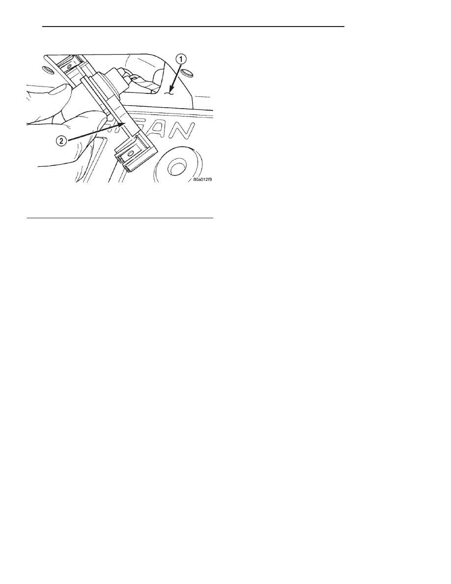
(3) Position the lamp (Fig. 13) and install retain-
ing screws (Fig. 12).
Fig. 13 License Plate Lamp
1 – REAR BUMPER FASCIA
2 – LICENSE PLATE LAMP
JX
LAMPS
8L - 17
REMOVAL AND INSTALLATION (Continued)
BULB APPLICATION
TABLE OF CONTENTS
page
page
SPECIFICATIONS
EXTERIOR LAMPS. . . . . . . . . . . . . . . . . . . . . . . . 18
TORQUE SPECIFICATIONS . . . . . . . . . . . . . . . . . 18
SPECIFICATIONS
EXTERIOR LAMPS
Back-up . . . . . . . . . . . . . . . . . . . . . . . . . . . P21–5W
Fog . . . . . . . . . . . . . . . . . . . . . . . . . . . . . . . . . 9006
Rear Fog . . . . . . . . . . . . . . . . . . . . . . . . . . . . P21W
Headlamp . . . . . . . . . . . . . . . . . . . . . . . . . . . . . H4
Park Lamp . . . . . . . . . . . . . . . . . . . . . . . . . . . W5W
Side Repeater . . . . . . . . . . . . . . . . . . . . . . . . . TW4
License Plate . . . . . . . . . . . . . . . . . . . . . . . . . W5W
Front Turn Signal . . . . . . . . . . . . . . . . . . . . PY21W
Tail/Stop . . . . . . . . . . . . . . . . . . . . . . . . . . . P21/5W
Turn Signal . . . . . . . . . . . . . . . . . . . . . . . . . . P21W
CHMSL Lamp . . . . . . . . . . . . . . . . . . . . 921W/16/W
TORQUE SPECIFICATIONS
DESCRIPTION
TORQUE
Headlamp Module
Fasteners . . . . . . . . . . . . . . . . . . 1 N·m (10 in. lbs.)
Tail lamp
Plastic Nuts . . . . . . . . . . . . . . . . 1 N·m (10 in. lbs.)
Rear Fog Lamp
Screws . . . . . . . . . . . . . . . . . . . . 1 N·m (10 in. lbs.)
8L - 18
LAMPS
JX
PASSIVE RESTRAINT SYSTEMS
TABLE OF CONTENTS
page
page
DESCRIPTION AND OPERATION
AIRBAG CONTROL MODULE (ACM) . . . . . . . . . . 1
CLOCKSPRING . . . . . . . . . . . . . . . . . . . . . . . . . . . 1
DRIVER AIRBAG MODULE . . . . . . . . . . . . . . . . . . 2
PASSENGER AIRBAG MODULE . . . . . . . . . . . . . . 2
SEATBELT CONTROL TIMER MODULE
(SCTM) . . . . . . . . . . . . . . . . . . . . . . . . . . . . . . . 3
STRUCTURAL SEAT BELT SYSTEM . . . . . . . . . . . 3
DIAGNOSIS AND TESTING
AIRBAG SYSTEM TEST . . . . . . . . . . . . . . . . . . . . 4
SEATBELT CONTROL TIMER MODULE
(SCTM) . . . . . . . . . . . . . . . . . . . . . . . . . . . . . . . 4
CONDITIONS . . . . . . . . . . . . . . . . . . . . . . . . . . . 5
SERVICE PROCEDURES
REMOVAL AND INSTALLATION
WARNINGS AND PRECAUTIONS . . . . . . . . . . . . . 8
AIRBAG CONTROL MODULE (ACM) . . . . . . . . . . 8
CLOCKSPRING . . . . . . . . . . . . . . . . . . . . . . . . . . . 9
DRIVER AIRBAG MODULE . . . . . . . . . . . . . . . . . 10
PASSENGER AIRBAG MODULE . . . . . . . . . . . . . 10
SEATBELT CONTROL TIMER MODULE
(SCTM) . . . . . . . . . . . . . . . . . . . . . . . . . . . . . . 11
STEERING WHEEL . . . . . . . . . . . . . . . . . . . . . . . 11
ADJUSTMENTS
CLOCKSPRING CENTERING PROCEDURE . . . . . 12
DESCRIPTION AND OPERATION
AIRBAG CONTROL MODULE (ACM)
DESCRIPTION
The Airbag Control Module (ACM) contains the
impact sensor and energy reserve capacitor. The
impact sensor acts as a threshold sensitive switch
that completes a circuit when an impact provides suf-
ficient deceleration. The sensor is calibrated for the
specific vehicle and reacts to the severity and direc-
tion of the impact.
OPERATION
The ACM monitors the system to determine the
system readiness. The ACM stores sufficient energy
to deploy the airbags for approximately two minutes
after the battery is disconnected. The ACM contains
on-board diagnostics, and illuminates the AIRBAG
warning lamp in the cluster when a diagnostic trou-
ble code occurs. The warning equipment is tested for
a few seconds every time the vehicle is started.
CLOCKSPRING
DESCRIPTION
The clockspring is mounted to the steering column
behind the steering wheel. The clockspring consists
of a flat, ribbon like, electrically conductive tape that
winds and unwinds with the steering wheel rotation.
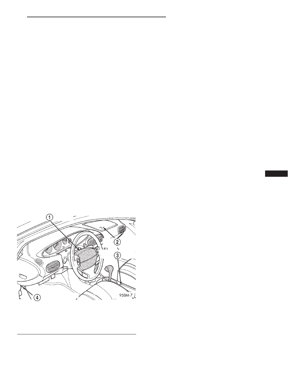
Fig. 1 Airbag Control Module (ACM) Location
1 – DRIVER AIRBAG MODULE
2 – PASSENGER AIRBAG MODULE
3 – AIRBAG CONTROL MODULE
4 – DATA LINK CONNECTOR
JX
PASSIVE RESTRAINT SYSTEMS
8M - 1
OPERATION
The clockspring is used to maintain a continuous
electrical circuit between the wiring harness and the:
• Driver’s airbag module
• Speed control switches
• Horn switch
DRIVER AIRBAG MODULE
WARNING: NEVER DISASSEMBLE THE DRIVER OR
PASSENGER AIRBAG MODULES, THERE ARE NO
SERVICEABLE PARTS WITHIN THE MODULES.
DESCRIPTION
The Driver Airbag Module located in the center of
the steering wheel is the most visible part of the sys-
tem. It contains the airbag cushion and its support-
ing components. The airbag module contains a
housing in which the cushion and inflator are
attached and sealed.
OPERATION
The driver side inflator assembly is mounted from
the back of the module housing. When supplied with
the proper electrical signal, the inflator assembly
produces a gas and discharges it directly into the
cushion. A protective cover is fitted to the front of the
Driver Airbag Module and forms a decorative cover
in the center of the steering wheel. The Driver Air-
bag Module is mounted directly to the steering
wheel.
PASSENGER AIRBAG MODULE
WARNING: NEVER DISASSEMBLE THE DRIVER OR
PASSENGER AIRBAG MODULES, THERE ARE NO
SERVICEABLE PARTS WITHIN THE MODULES.
DESCRIPTION
The Passenger Airbag Module is located beneath
the decorative cover of the instrument panel, facing
the passenger seat.
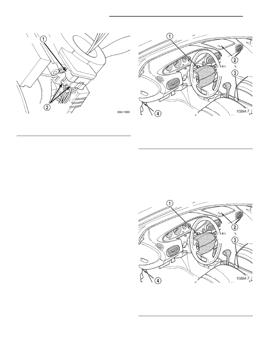
Fig. 2 Clockspring Location
1 – CLOCKSPRING
2 – WIRING HARNESS CONNECTORS
Fig. 3 Driver Airbag Module
1 – DRIVER AIRBAG MODULE
2 – PASSENGER AIRBAG MODULE
3 – AIRBAG CONTROL MODULE
4 – DATA LINK CONNECTOR
Fig. 4 Passenger Airbag Module
1 – DRIVER AIRBAG MODULE
2 – PASSENGER AIRBAG MODULE
3 – AIRBAG CONTROL MODULE
4 – DATA LINK CONNECTOR
8M - 2
PASSIVE RESTRAINT SYSTEMS
JX
DESCRIPTION AND OPERATION (Continued)
Нет комментариевНе стесняйтесь поделиться с нами вашим ценным мнением.
Текст