
Chrysler Stratus Convertible. Manual — part 232
CHARGING SYSTEM
TABLE OF CONTENTS
page
page
DESCRIPTION AND OPERATION
CHARGING SYSTEM. . . . . . . . . . . . . . . . . . . . . . . 1
GENERATOR . . . . . . . . . . . . . . . . . . . . . . . . . . . . . 1
BATTERY TEMPERATURE SENSOR . . . . . . . . . . . 2
ELECTRONIC VOLTAGE REGULATOR . . . . . . . . . . 2
ON-BOARD DIAGNOSTIC SYSTEM . . . . . . . . . . . 2
REMOVAL AND INSTALLATION
SPECIFICATIONS
DESCRIPTION AND OPERATION
CHARGING SYSTEM
DESCRIPTION
The charging system consists of:
• Generator
• Electronic Voltage Regulator (EVR) circuitry
within the Powertrain Control Module (PCM)
• Ignition switch (refer to the Ignition System for
information)
• Battery (refer to the Battery for information)
• Battery temperature sensor
• Wiring harness and connections (refer to the
Wiring for information)
OPERATION
The charging system is turned on and off with the
ignition switch. When the ignition switch is turned to
the ON position, battery voltage is applied to the
generator rotor through one of the two field termi-
nals to produce a magnetic field. The generator is
driven by the engine through a serpentine belt and
pulley arrangement.
The amount of DC current produced by the gener-
ator is controlled by the EVR (field control) circuitry,
contained within the PCM. This circuitry is con-
nected in series with the second rotor field terminal
and ground.
Temperature data, along with data from monitored
line voltage, is used by the PCM to vary the battery
charging rate. This is done by cycling the ground
path to control the strength of the rotor magnetic
field. The PCM then compensates and regulates gen-
erator current output accordingly and to maintain
the proper voltage depending on battery tempera-
ture.
All vehicles are equipped with On-Board Diagnos-
tics (OBD). All OBD-sensed systems, including the
EVR (field control) circuitry, are monitored by the
PCM. Each monitored circuit is assigned a Diagnos-
tic Trouble Code (DTC). The PCM will store a DTC in
electronic memory for any failure it detects.
GENERATOR
DESCRIPTION
The generator is belt-driven by the engine. It is
serviced only as a complete assembly. If the genera-
tor fails for any reason, the entire assembly must be
replaced.
OPERATION
As the energized rotor begins to rotate within the
generator, the spinning magnetic field induces a cur-
rent into the windings of the stator coil. Once the
generator begins producing sufficient current, it also
provides the current needed to energize the rotor.
The Y type stator winding connections deliver the
induced AC current to 3 positive and 3 negative
diodes for rectification. From the diodes, rectified DC
current is delivered to the vehicles electrical system
through the generator, battery, and ground terminals.
Noise emitting from the generator may be caused
by:
• Worn, loose or defective bearings
• Loose or defective drive pulley
• Incorrect, worn, damaged or misadjusted drive
belt
• Loose mounting bolts
• Misaligned drive pulley
• Defective stator or diode
• Damaged internal fins
JX
CHARGING SYSTEM
8C - 1
BATTERY TEMPERATURE SENSOR
DESCRIPTION
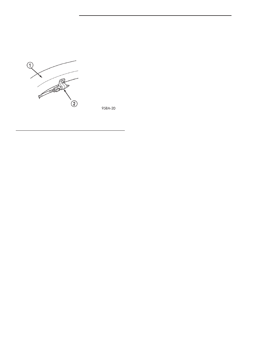
The sensor is located on the rear side of the front
bumper beam. (Fig. 1).
OPERATION
The battery temperature sensor is used to deter-
mine the battery temperature. This temperature
data, along with data from monitored line voltage, is
used by the PCM to vary the battery charging rate.
System voltage will be higher at colder temperatures
and is gradually reduced at warmer temperatures.
The battery temperature sensor is also used for
OBD II diagnostics. Certain faults and OBD II mon-
itors are either enabled or disabled depending upon
the battery temperature sensor input (example: dis-
able purge and EGR, enable LDP). Most OBD II
monitors are disabled below 20°F.
ELECTRONIC VOLTAGE REGULATOR
DESCRIPTION
The Electronic Voltage Regulator (EVR) is not a
separate component. It is actually a voltage regulat-
ing circuit located within the Powertrain Control
Module (PCM). The EVR is not serviced separately. If
replacement is necessary, the PCM must be replaced.
OPERATION
The amount of DC current produced by the gener-
ator is controlled by EVR circuitry contained within
the PCM. This circuitry is connected in series with
the generators second rotor field terminal and its
ground.
Voltage is regulated by cycling the ground path to
control the strength of the rotor magnetic field. The
EVR circuitry monitors system line voltage (B+) and
battery temperature (refer to Battery Temperature
Sensor for more information). It then determines a
target charging voltage. If sensed battery voltage is
0.5 volts or lower than the target voltage, the PCM
grounds the field winding until sensed battery volage
is 0.5 volts above target voltage. A circuit in the PCM
cycles the ground side of the generator field up to
100 times per second (100Hz), but has the capability
to ground the field control wire 100% of the time (full
field) to achieve the target voltage. If the charging
rate cannot be monitored (limp-in), a duty cycle of
25% is used by the PCM in order to have some gen-
erator output. Also refer to Charging System Opera-
tion for additional information.
ON-BOARD DIAGNOSTIC SYSTEM
OPERATION
GENERAL INFORMATION
The Powertrain Control Module (PCM) monitors
critical input and output circuits of the charging sys-
tem, making sure they are operational. A Diagnostic
Trouble Code (DTC) is assigned to each input and
output circuit monitored by the OBD system. Some
circuits are checked continuously and some are
checked only under certain conditions.
If the OBD system senses that a monitored circuit
is bad, it will put a DTC into electronic memory. The
DTC will stay in electronic memory as long as the
circuit continues to be bad. The PCM is programmed
to clear the memory after 50 engine starts if the
problem does not occur again.
DIAGNOSTIC TROUBLE CODES
A DTC description can be read using the DRB scan
tool. Refer to the appropriate Powertrain Diagnostic
Procedures manual for information.
A DTC does not identify which component in a cir-
cuit is bad. Thus, a DTC should be treated as a
symptom, not as the cause for the problem. In some
cases, because of the design of the diagnostic test
procedure, a DTC can be the reason for another DTC
to be set. Therefore, it is important that the test pro-
cedures be followed in sequence, to understand what
caused a DTC to be set.
ERASING DIAGNOSTIC TROUBLE CODES
The DRB Scan Tool must be used to erase a DTC.
Fig. 1 Battery Temperature Sensor
1 – BUMPER BEAM
2 – BATTERY TEMPERATURE SENSOR
8C - 2
CHARGING SYSTEM
JX
DESCRIPTION AND OPERATION (Continued)
REMOVAL AND INSTALLATION
GENERATOR—2.5L
REMOVAL
(1) Disconnect battery negative cable from remote
negative terminal on shock tower.
(2) Unplug field circuit from generator.
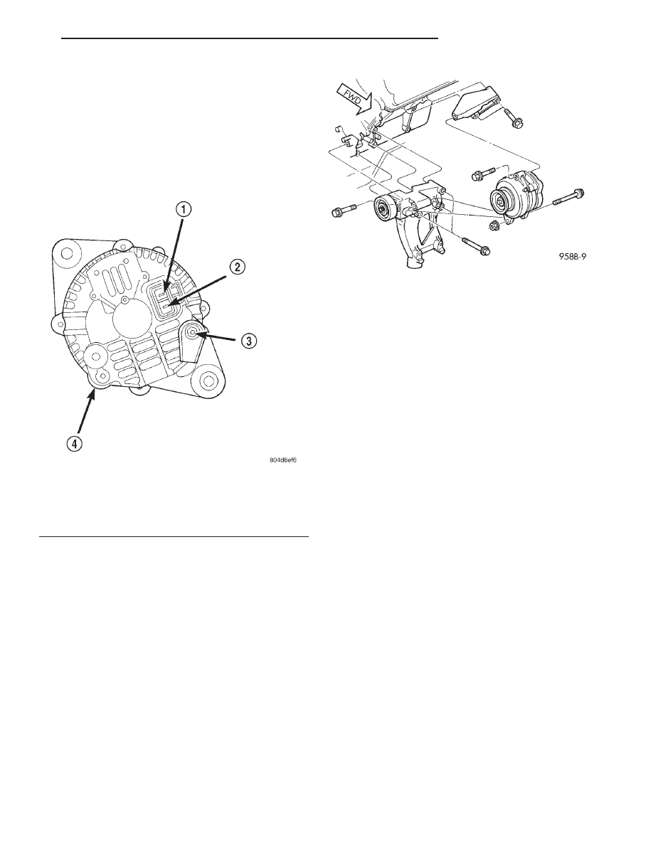
(3) Remove the B+ terminal nut and wire (Fig. 2).
(4) Loosen top mounting ear bolt.
(5) Loosen pivot bolt, but do not remove. Be care-
ful not to lose nut (Fig. 3).
(6) Loosen adjusting bolt on idler to allow removal
of the generator drive belt. Refer to the Cooling Sys-
tem.
(7) Remove pivot bolt, do not drop spacer.
(8) Remove top mounting ear bolt.
(9) Remove upper generator bracket.
(10) Remove generator.
INSTALLATION
(1) Install generator.
(2) Install upper generator bracket.
(3) Install top mounting ear bolt.
(4) Install pivot bolt, do not drop spacer.
(5) Install field circuit to generator.
(6) Install the B+ terminal nut and wire (Fig. 2).
(7) Tighten adjusting bolt on idler for the genera-
tor drive belt. Refer to the Cooling System.
(8) Tighten the top mounting ear bolt.
(9) Tighten the pivot bolt (Fig. 3).
(10) Connect battery negative cable to the remote
negative terminal on shock tower.
BATTERY TEMPERATURE SENSOR
REMOVAL
(1) Remove the negative battery cable.
(2) Remove the front bumper fascia, refer to the
Frame and Bumper section.
(3) Raise vehicle on host.
(4) Remove sensor.
(5) Disconnect electrical connector from sensor.
INSTALLATION
(1) Connect electrical connector to sensor.
(2) Install sensor.
(3) Lower vehicle.
(4) Install the front bumper fascia, refer to the
Frame and Bumper section.
(5) Install the negative battery cable.
Fig. 2 Wiring Connections—2.5L
1 – FEED
2 – TO POWERTRAIN CONTROL MODULE
3 – B+ TERMINAL
4 – CASE GROUND
Fig. 3 Generator—2.5L Engine
JX
CHARGING SYSTEM
8C - 3
SPECIFICATIONS
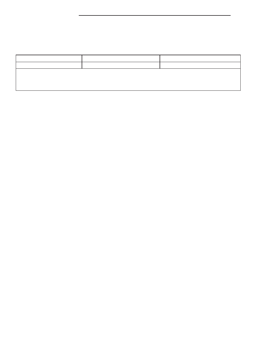
GENERATOR RATINGS
TYPE
ENGINES
MINIMUM TEST AMPS
DENSO
2.5L
74 amps
The Test Specifications are:
1. 2500
6
20 RPMS
2. Voltage Output 14V
6
.5V
3. Field Current 5amps
6
.1amp
TORQUE
DESCRIPTION
TORQUE
Battery Terminal Nut . . . . . . . . 10 N·m (90 in. lbs.)
Battery Hold Down Clamp
Bolt . . . . . . . . . . . . . . . . . . . 10 N·m (90 in. lbs.)
Battery Negative Cable Nut at
Shock Tower . . . . . . . . . . . . . 10 N·m (90 in. lbs.)
Generator B+ Terminal . . . . . . . 9 N·m (75 in. lbs.)
Generator Mounting Bolt . . . . . 54 N·m (40 ft. lbs.)
Generator Pivot Bolt . . . . . . . . . 54 N·m (40 ft. lbs.)
8C - 4
CHARGING SYSTEM
JX
Нет комментариевНе стесняйтесь поделиться с нами вашим ценным мнением.
Текст