
Chrysler Stratus Convertible. Manual — part 200
(2) Connect the wiring harness connector to the
brake lamp switch.
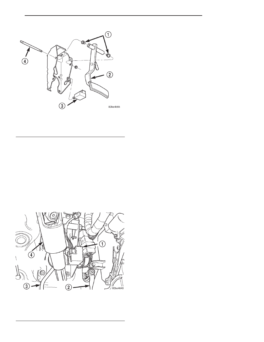
(3) Install the brake lamp switch in the brake
pedal bracket (Fig. 155). Install it using the following
procedure:
• Depress the brake pedal as far down as possible.
• Install the switch in its bracket by aligning the
index tab on the switch with the slot in the mounting
bracket.
• When the switch is fully seated in its bracket,
rotate the switch clockwise approximately 30° to lock
the switch into place. It should be aligned straight up
and down (Fig. 156).
CAUTION: Do not use excessive force when pulling
back on the brake pedal to adjust the brake lamp
switch. If too much force is used, the switch or
striker can be damaged.
(4) Gently release/pull back on the brake pedal
until the pedal stops moving. This will ratchet the
switch plunger backward to the correct adjustment
position.
(5) Check the brake lamps to verify they are oper-
ating properly and not staying on when the pedal is
in the released position.
DISASSEMBLY AND ASSEMBLY
MASTER CYLINDER BRAKE FLUID RESERVOIR
NOTE: To replace the master cylinder brake fluid
reservoir on this vehicle, it is not necessary to
remove the master cylinder from the power brake
booster.
DISASSEMBLY
(1) Remove master cylinder from vehicle. Refer to
REMOVAL AND INSTALLATION in this section.
(2) Using Mopar, Brake Parts Cleaner or an equiv-
alent, thoroughly clean the master cylinder and
brake fluid reservoir.
(3) Remove the brake fluid reservoir filler cap.
(4) Using a syringe or equivalent type tool, empty
as much brake fluid as possible from the reservoir.
CAUTION: Do not pry fluid reservoir off master cyl-
inder using a tool, damage to the reservoir or mas-
ter cylinder can result.
(5) Remove brake fluid reservoir from master cyl-
inder by rocking the reservoir from side to side while
pulling upward on the fluid reservoir.
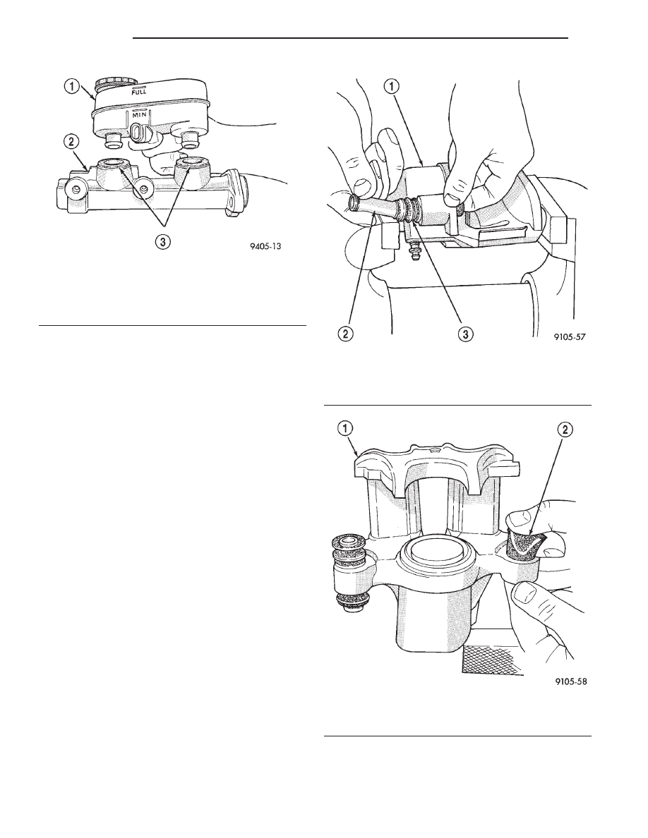
(6) Remove master cylinder housing to brake fluid
reservoir sealing grommets (Fig. 157).
ASSEMBLY
CAUTION: To ensure a leak proof seal when install-
ing a fluid reservoir, never reuse the original fluid
reservoir to master cylinder sealing grommets.
(1) Install new master cylinder housing to brake
fluid reservoir sealing grommets (Fig. 157) in master
cylinder housing.
(2) Lubricate reservoir mounting area with fresh
clean brake fluid. Place reservoir in position over
grommets. Seat reservoir into grommets using a
rocking motion while firmly pressing down on fluid
reservoir.
Fig. 155 Switch And Bracket
1 – BUSHINGS
2 – BRAKE PEDAL
3 – BRAKE LAMP SWITCH
4 – PIVOT SHAFT
Fig. 156 Brake Lamp Switch
1 – SWITCH
2 – ACCELERATOR PEDAL
3 – BRAKE PEDAL
4 – STEERING COLUMN INTERMEDIATE SHAFT
JX
BRAKES
5 - 63
REMOVAL AND INSTALLATION (Continued)
(3) Be sure reservoir is positioned properly.
(4) Make sure bottom of fluid reservoir touches top
of both sealing grommets.
(5) Reinstall the master cylinder on the vehicle.
Refer to REMOVAL AND INSTALLATION in this
section.
DISC BRAKE CALIPER (FRONT AND REAR)
Before disassembling the brake caliper, clean and
inspect it. Refer to CLEANING AND INSPECTION
in this section of this service manual group.
CALIPER GUIDE PIN BUSHING
REMOVAL
(1) With one hand, push the guide pin bushing
sleeve towards the back of the caliper, and at the
same time, pull the sleeve out the back of the caliper
and bushing (Fig. 158).
(2) Using your fingers, collapse one side of the rub-
ber guide pin bushing. Pull the guide pin bushing out
the other side of the brake caliper mounting boss
(Fig. 159).
Fig. 157 Removing Fluid Reservoir From Master
Cylinder
1 – FLUID RESERVOIR
2 – MASTER CYLINDER
3 – GROMMET
Fig. 158 Removing Sleeve From Bushing
1 – CALIPER
2 – SLEEVE
3 – BUSHING
Fig. 159 Removing Bushing From Caliper
1 – CALIPER
2 – BUSHING
5 - 64
BRAKES
JX
DISASSEMBLY AND ASSEMBLY (Continued)
INSTALLATION
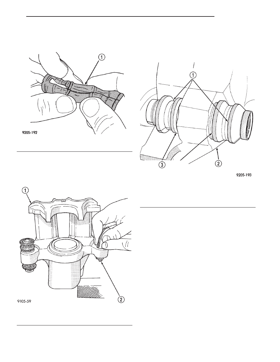
(1) Fold the guide pin bushing in half lengthwise
at the solid middle section (Fig. 160).
NOTE: To avoid damage to the bushing, do not use
a sharp object to install the guide pin bushing.
(2) Insert the folded bushing into the caliper
mounting boss using your fingers (Fig. 161).
(3) Unfold the bushing using your fingers or a
wooden dowel until the bushing is fully seated into
the caliper housing. The bushing flanges should be
seated evenly on both sides of the bushing hole (Fig.
162).
(4) Lubricate the inside surfaces of the bushing
using Mopar Dielectric Grease or an equivalent.
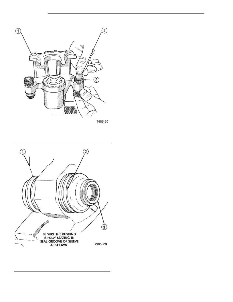
(5) Install the guide pin sleeve into one end of
bushing until the seal area of bushing is past the
seal groove in the sleeve (Fig. 163).
(6) Holding the convoluted boot on the opposite
end of the bushing, push the steel sleeve through the
bushing until the bushing boot is fully seated into
the seal groove on that end of sleeve (Fig. 163).
Install the other end bushing boot into the groove on
that end of the bushing sleeve.
(7) Verify both ends of the bushing are seated in
the sleeve groves (Fig. 164). When the sleeve is
seated properly into the bushing, the sleeve/bushing
can be held between your fingers and easily slid back
and forth without the bushing unseating from the
sleeve groove.
Fig. 160 Folded Caliper Guide Pin Bushing
1 – CALIPER GUIDE PIN BUSHING
Fig. 161 Installing Caliper Guide Pin Bushing
1 – CALIPER
2 – BUSHING
Fig. 162 Bushing Correctly Installed In Caliper
1 – BUSHING
2 – CALIPER
3 – BE SURE BOTH BUSHING FLANGES ARE FULLY SEATED
AROUND CALIPER BUSHING BORES.
JX
BRAKES
5 - 65
DISASSEMBLY AND ASSEMBLY (Continued)
CALIPER PISTON AND SEALS
CALIPER PISTON REMOVAL
WARNING: UNDER NO CONDITION SHOULD HIGH
PRESSURE AIR EVER BE USED TO REMOVE A PIS-
TON FROM A CALIPER BORE. PERSONAL INJURY
COULD RESULT FROM SUCH A PRACTICE.
NOTE: The safest way to remove the piston from
the caliper bore is to use the hydraulic pressure of
the vehicle’s brake system.
(1) Following the removal procedure in DISC
BRAKE SHOES found in this section, remove the
caliper from the brake rotor and hang the assembly
on a wire hook away from rotor and body of the vehi-
cle so brake fluid cannot get on these components.
Remove the brake shoes, and place a small piece of
wood between the piston and caliper fingers.
(2) Carefully depress the brake pedal to hydrauli-
cally push piston out of its bore. Once completed,
apply and hold down the brake pedal to any position
beyond the first inch of pedal travel using a brake
pedal holding tool. This will prevent the fluid in the
master cylinder reservoir from completely draining
out.
(3) Disconnect the brake fluid flex hose from the
caliper assembly and remove it from the vehicle.
CALIPER SEAL REMOVAL
CAUTION: Do not use excessive force when clamp-
ing caliper in vise. Excessive vise pressure will
cause bore distortion.
(1) To disassemble the caliper, mount it in a vise
equipped with protective jaws.
(2) Remove the piston dust boot from the caliper
and discard (Fig. 165).
NOTE: Do not use a screw driver or other metal
tool for seal removal. Using such tools can scratch
the bore or leave burrs on the seal groove edges.
(3) Using a soft tool such as a plastic trim stick,
work the piston seal out of its groove in caliper pis-
ton bore (Fig. 166). Discard the old seal.
(4) Clean the piston bore and drilled passage ways
using alcohol or a suitable solvent. Wipe it dry using
only a lint-free cloth.
Fig. 163 Installing Sleeve In Bushing
1 – CALIPER
2 – SLEEVE
3 – BUSHING
Fig. 164 Correctly Installed Guide Pin Sleeve And
Bushing
1 – CALIPER
2 – BUSHING
3 – SLEEVE
5 - 66
BRAKES
JX
DISASSEMBLY AND ASSEMBLY (Continued)
Нет комментариевНе стесняйтесь поделиться с нами вашим ценным мнением.
Текст