
Chrysler Stratus Convertible. Manual — part 260
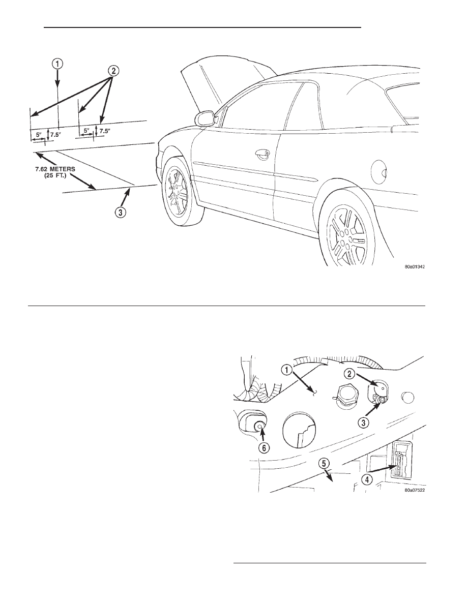
(7) Measure distance from the center line of the
vehicle to the center of each headlamp being aligned.
Transfer measurements to screen (with tape) to each
side of vehicle center line. Use these lines for left/
right adjustment reference.
HEADLAMP ADJUSTMENT
A properly aimed low beam headlamp will project
the center of the low beam hot spot on the alignment
screen 190 mm (7.5 in.) below the headlamp center
line. The side-to-side low beam hot spot should be
127 mm (5 in.) right of headlamp center line (Fig. 3).
The preferred headlamp alignment is 0 (
60.76°)
for the up/down adjustment as indicated on
bubble level. Preferred left/right alignment is 0
(
60.76°) as indicated on the gauge wheel. The
high beam headlamps cannot be aligned. The high
beam pattern should be correct when the low beams
are aligned properly.
NOTE: The bubble level and gauge wheel is cali-
brated before the headlamp is installed in the vehi-
cle. The bubble level cannot be calibrated without
damaging the headlamp module. If bubble level is
faulty, replace headlamp module.
To adjust headlamp alignment, rotate alignment
screws to achieve the specified low beam hot spot
pattern (Fig. 4).
Fig. 3 Headlamp Alignment Screen
1 – CENTER OF VEHICLE
2 – CENTER OF HEADLAMPS
3 – FRONT OF HEADLAMP
Fig. 4 Headlamp Alignment Screws
1 – RADIATOR CLOSURE PANEL
2 – GAUGE WHEEL
3 – LEFT/RIGHT ADJUSTER
4 – BUBBLE VIAL
5 – HEADLAMP MODULE
6 – UP/DOWN ADJUSTER
JX
LAMPS
8L - 5
ADJUSTMENTS (Continued)
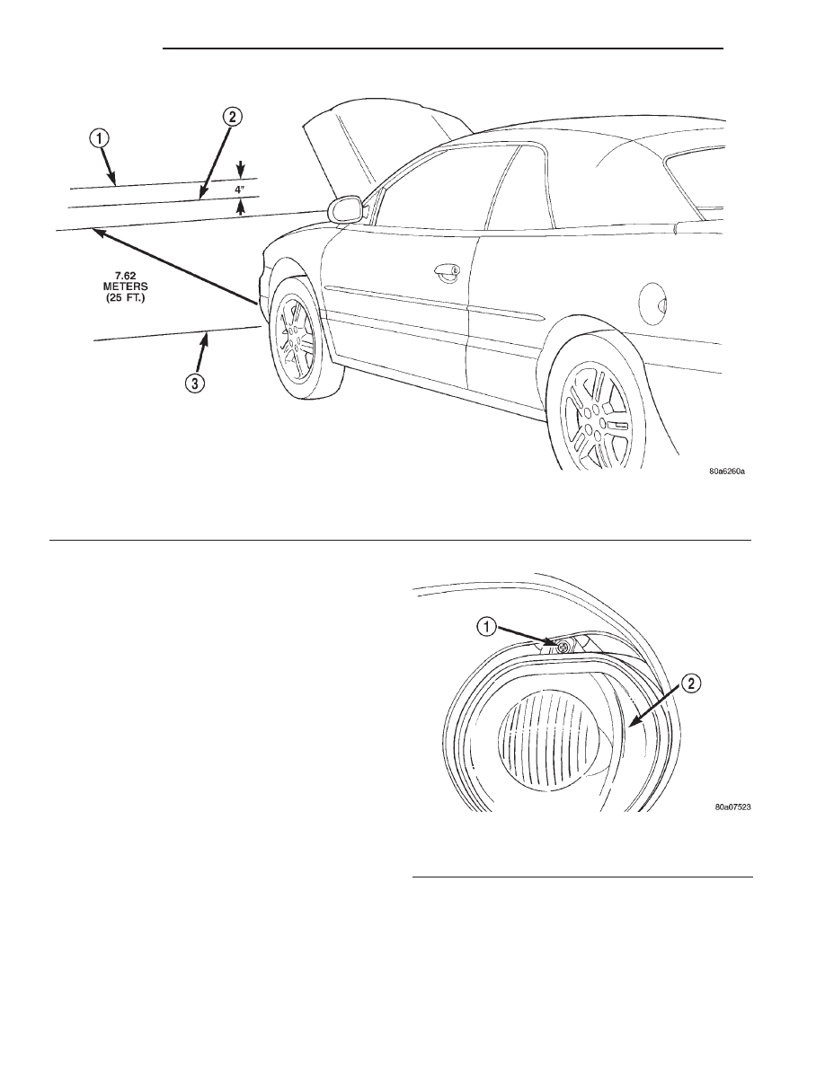
FOG LAMP ALIGNMENT
Prepare a alignment screen (Fig. 5). Refer to Align-
ment Screen Preparation paragraph in this section. A
properly aligned fog lamp will project a pattern on
the alignment screen 100 mm (4 in.) below the fog
lamp center line and straight ahead.
To adjust fog lamp alignment, rotate alignment
screw to achieve the specified hot spot pattern (Fig.
6).
Fig. 5 Fog Lamp Alignment
1 – CENTER OF FOGLAMP
2 – TOP OF BEAM PATTERN
3 – FRONT OF FOGLAMP
Fig. 6 Fog Lamp Adjuster
1 – UP/DOWN ADJUSTER
2 – FOGLAMP
8L - 6
LAMPS
JX
ADJUSTMENTS (Continued)
EXTERIOR LAMP SWITCHES
TABLE OF CONTENTS
page
page
REMOVAL AND INSTALLATION
HEADLAMP SWITCH . . . . . . . . . . . . . . . . . . . . . . . 7
HEADLAMP DIMMER SWITCH. . . . . . . . . . . . . . . . 7
REMOVAL AND INSTALLATION
HEADLAMP SWITCH
Service procedures for the headlamp switch can be
found in Group 8E, Instrument Panel and Gauges.
More information can be found in Group 8W, Wiring
Diagrams.
HEADLAMP DIMMER SWITCH
The headlamp dimmer switch is incorporated into
the turn signal switch. Proper procedures can be
found in Group 8J, Turn Signal and Flashers. More
information can be found in Group 8W, Wiring Dia-
grams.
JX
LAMPS
8L - 7
LAMP BULB SERVICE
TABLE OF CONTENTS
page
page
REMOVAL AND INSTALLATION
HEADLAMP BULB . . . . . . . . . . . . . . . . . . . . . . . . . 8
FOG LAMP BULB. . . . . . . . . . . . . . . . . . . . . . . . . . 8
PARK AND TURN SIGNAL LAMP BULB . . . . . . . . . 9
CENTER HIGH MOUNTED STOP LAMP
(CHMSL) BULB . . . . . . . . . . . . . . . . . . . . . . . . . . 9
TAIL, BRAKE AND TURN SIGNAL LAMP
BULBS . . . . . . . . . . . . . . . . . . . . . . . . . . . . . . . . 9
BACK-UP LAMP BULB . . . . . . . . . . . . . . . . . . . . . 10
LICENSE PLATE LAMP BULB . . . . . . . . . . . . . . . 10
DOOR COURTESY LAMP BULB. . . . . . . . . . . . . . 10
FRONT MAP LAMP BULB . . . . . . . . . . . . . . . . . . 10
ASH RECEIVER/CUP HOLDER LAMP BULB . . . . 11
FLOOR CONSOLE COURTESY LAMP BULB . . . . 11
LIGHTED TRANSMISSION RANGE INDICATOR
LETTER BEZEL LAMP. . . . . . . . . . . . . . . . . . . . 11
REMOVAL AND INSTALLATION
HEADLAMP BULB
REMOVAL
CAUTION: Do not touch the glass of halogen bulbs
with fingers or other possibly oily surface, reduced
bulb life will result.
(1) Release hood latch and open hood.
(2) Remove screws attaching headlamp module to
radiator closure panel.
(3) Remove headlamp module from radiator clo-
sure panel.
(4) Rotate retaining ring counterclockwise one
quarter turn.
(5) Disconnect wire connector from back of head-
lamp bulb.
(6) Remove retaining ring from headlamp module.
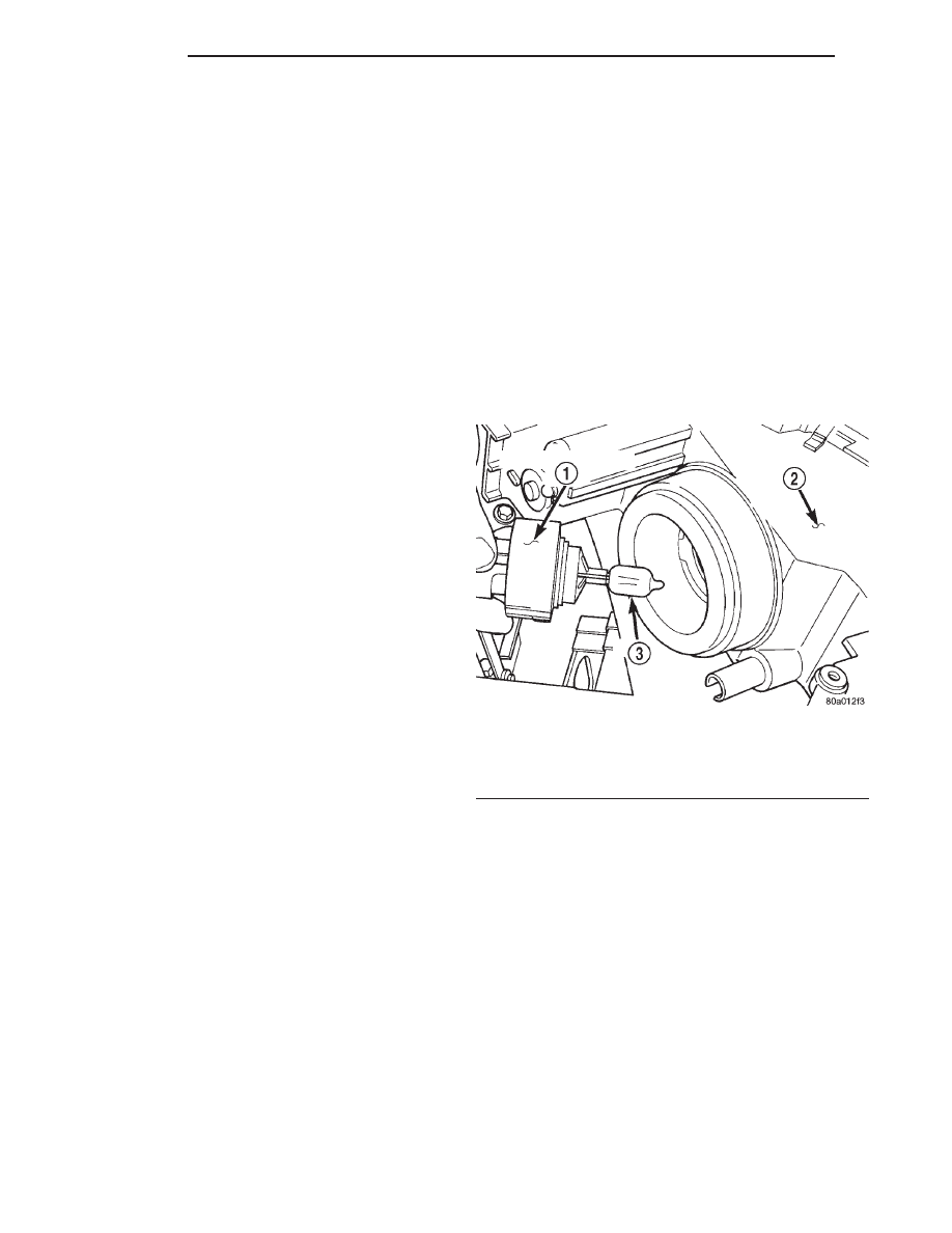
(7) Pull bulb from headlamp module (Fig. 1).
INSTALLATION
(1) Insert bulb into headlamp module.
(2) Position retaining ring to headlamp module.
(3) Rotate retaining ring clockwise one quarter
turn.
(4) Connect wire connector from back of headlamp
bulb.
(5) Position headlamp module to radiator closure
panel.
(6) Install screws attaching headlamp module to
radiator closure panel.
(7) Verify proper headlamp alignment. Adjust as
necessary.
FOG LAMP BULB
REMOVAL
(1) Raise vehicle with suitable lifting device. Refer
to Group 0, Lubrication and Maintenance, for proper
procedures.
(2) Rotate bulb one quarter turn counterclockwise.
(3) Pull bulb from back of fog lamp (Fig. 2).
(4) Disconnect wire connector from bulb.
INSTALLATION
(1) Connect wire connector to fog lamp bulb.
(2) Push bulb into back of fog lamp.
(3) Rotate bulb one quarter turn clockwise.
(4) Lower vehicle.
Fig. 1 Headlamp Bulb
1 – BULB RETAINING RING
2 – HEADLAMP MODULE
3 – BULB
8L - 8
LAMPS
JX
Нет комментариевНе стесняйтесь поделиться с нами вашим ценным мнением.
Текст