
Chrysler Stratus Convertible. Manual — part 278
PROGRAMMING BLANK SENTRY KEY
TRANSPONDERS WITH A DRB lll
T SCAN TOOL
When programming a blank Sentry Key transpon-
der, the key blank must first be cut to match the
ignition lock cylinder. It will also be necessary to
enter the vehicle’s four digit PIN code into the DRB
lll
t scan tool to enter the Sentry Key Immobilizer
Module’s (SKIM’s) secured access mode.
NOTE: Once a Sentry Key is programmed to a par-
ticular vehicle, it cannot be transferred to another
vehicle.
Insert the blank key into the ignition and turn it to
the RUN position. Using the DRB lll
t scan tool,
select “Theft Alarm,” then “SKIM,” then “Miscella-
neous.” Select “Program New Key.” Enter the four
digit PIN code using the DRB lll
t. When program-
ming is completed, the SKIM will exit secured access
mode and display the status of the key. One of five
different status messages may be displayed as fol-
lows:
• “Programming Successful” is displayed if SKIM
Sentry Key programming succeeds.
• “Learned Key in Ignition” is displayed if the key
in the ignition has already been programmed into
that vehicle’s SKIM.
• “8 Keys Already Learned (At The Maximum)
Programming Not Done” is displayed if eight keys
have already been programmed into the SKIM. In
this case, if a new key needs to be added due to a
lost or defective key, the “Erase All Keys” function
(requires entering secured access mode) has to be
performed. Then the customer is seven keys plus the
new key MUST be reprogrammed into the SKIM.
• “Programming Not Attempted” is displayed after
an “Erase All Keys” function is executed.
• “Programming Key Failed” is displayed if fur-
ther diagnosis is required.
• To learn additional keys, turn the ignition OFF,
remove the learned key, and insert the next new
blank key. Turn ignition to the RUN position and re-
enter the secured access mode function and repeat
the “Program New Key” procedure outlined above.
REMOVAL AND INSTALLATION
BODY CONTROL MODULE (BCM)
For service of the Body Control Module (BCM),
Refer to Group 8E, Instrument Panel and Systems
for Removal and Installation.
NOTE: If BCM is replaced, the VTSS must be
enabled in the new BCM via the DRB lll
T
, in order to
start the vehicle.
JUNCTION BLOCK (JB)
Refer to Group 8O, Power Distribution Systems for
Removal and Installation.
SENTRY KEY IMMOBILIZER MODULE (SKIM)
WARNING: ON VEHICLES EQUIPPED WITH AIR-
BAGS,
REFER
TO
GROUP
8M
-
PASSIVE
RESTRAINT SYSTEMS BEFORE ATTEMPTING ANY
STEERING
WHEEL,
STEERING
COLUMN,
OR
INSTRUMENT PANEL COMPONENT DIAGNOSIS OR
SERVICE. FAILURE TO TAKE THE PROPER PRE-
CAUTIONS COULD RESULT IN ACCIDENTAL AIR-
BAG DEPLOYMENT AND POSSIBLE PERSONAL
INJURY.
REMOVAL
(1) Disconnect and isolate the battery negative
remote cable (Fig. 3).
(2) Remove knee bolster. Refer to Group 8E,
Instrument Panel and Systems for Removal and
Installation.
(3) Remove the steering column upper and lower
shrouds. Refer to Group 19, Steering for Removal
and Installation.
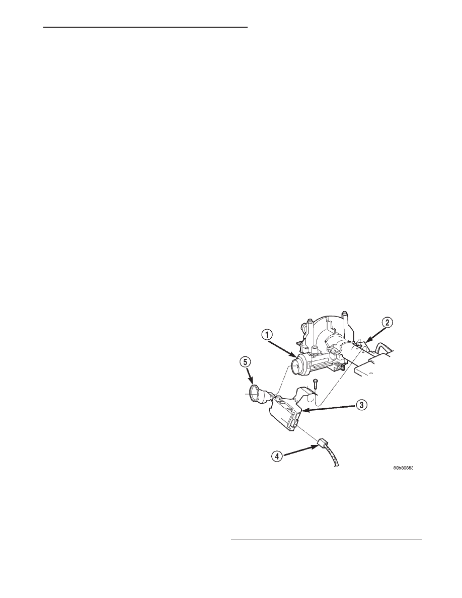
(4) Disengage the steering column wire harness
from the Sentry Key Immobilizer Module (SKIM).
Fig. 4 Sentry Key Immobilizer Module (SKIM)
Remove / Install
1 – IGNITION KEY CYLINDER
2 – STEERING COLUMN
3 – SENTRY KEY IMMOBILIZER MODULE (SKIM)
4 – SKIM CONNECTOR
5 – SKIM ANTENNA
JX
VEHICLE THEFT/SECURITY SYSTEMS
8Q - 7
SERVICE PROCEDURES (Continued)
(5) Remove the two screws securing the SKIM
module to the top of the steering column.
(6) Rotate the SKIM and its mounting bracket
upwards and then to the side away from the steering
column to slide the SKIM antenna ring from around
the ignition switch lock cylinder housing.
(7) Remove the SKIM from the vehicle.
INSTALLATION
(1) For installation, reverse the above procedures.
(2) If the SKIM is replaced with a new unit, a
DRB lll
t scan tool MUST be used to initialize the
new SKIM and to program at least two Sentry Key
transponders. Refer to Sentry Key Immobilizer Mod-
ule Initialization in this section.
VEHICLE THEFT/SECURITY SYSTEM (VTSS)
DECK LID SECURITY SWITCH
The Vehicle Theft Security System (VTSS) Deck
Lid Security Switch is part of the deck lid latch. If
replacement of the deck lid security switch is
required, the deck lid latch will need to be replaced.
Refer to Group 23, Body for deck lid latch Removal
and Installation.
VEHICLE THEFT/SECURITY SYSTEM (VTSS)
DOOR CYLINDER LOCK SWITCH
REMOVAL
(1) Disconnect and isolate the battery negative
remote cable.
(2) Refer to Group 23, Body for door trim and
water shield Removal and Installation.
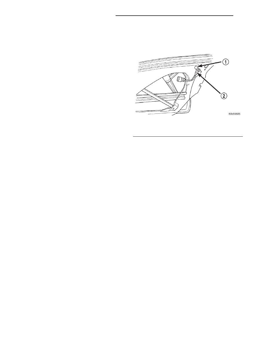
(3) Remove illuminated entry switch wiring clip
and disconnect connector (Fig. 5).
(4) Remove disarming switch from door handle.
INSTALLATION
For installation reverse above procedures.
Fig. 5 VTSS Door Cylinder Lock Switch Location
1 – KEY CYLINDER
2 – DOOR KEY CYLINDER SWITCH
8Q - 8
VEHICLE THEFT/SECURITY SYSTEMS
JX
REMOVAL AND INSTALLATION (Continued)
POWER SEAT SYSTEMS
TABLE OF CONTENTS
page
page
DESCRIPTION AND OPERATION
POWER SEAT SYSTEMS . . . . . . . . . . . . . . . . . . . 1
DIAGNOSIS AND TESTING
REMOVAL AND INSTALLATION
FRONT SEAT ASSEMBLY . . . . . . . . . . . . . . . . . . . 2
POWER FRONT SEAT ADJUSTER . . . . . . . . . . . . 2
POWER FRONT SEAT SWITCH . . . . . . . . . . . . . . 3
DESCRIPTION AND OPERATION
POWER SEAT SYSTEMS
DESCRIPTION
Power seats can be adjusted in 6 different direc-
tions:
• Up or down
• Forward or back
• Tilt forward or rearward
OPERATION
Two single armature permanent magnet reversible
motors are coupled through cables to worm gear box
assemblies. They are located in the seat tracks and
upper supports. The two single gear motor assem-
blies attach to the seat tracks and provide the vari-
ous seat movements.
The electrical circuit is protected by a 20 amp cir-
cuit breaker located in the junction block.
DIAGNOSIS AND TESTING
DIAGNOSTIC PROCEDURE
Before any testing is attempted the battery should
be carefully charged and all connections and termi-
nals cleaned and tightened to insure proper continu-
ity and grounds.
With dome lamp on, apply switch in direction of
failure. If dome lamp dims the seat motor is trying to
work indicating mechanical jamming. If dome lamp
does not dim, then proceed with the following electri-
cal tests.
CIRCUIT BREAKER
Find the correct circuit breaker in the junction
block. Pull out slightly but be sure that circuit
breaker terminals still contact terminals in junction
block. Connect ground wire of voltmeter to a good
ground. With probe of voltmeter positive wire, check
both terminals of circuit breaker for battery voltage.
If only one terminal checks at battery voltage, circuit
breaker is defective and must be replaced. If neither
terminal shows battery voltage, check for open or
shorted circuit to circuit breaker.
SEAT MOTOR
(1) Remove power seat switch from seat.
(2) Disconnect wire harness connector.
(3) Check Pin A for battery voltage and Pin B for
ground.
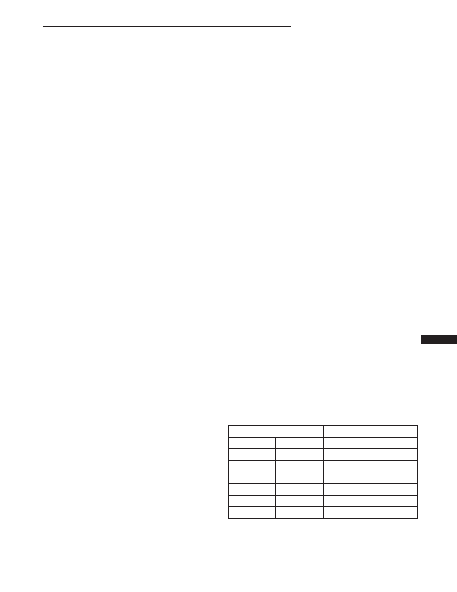
(4) To test the seat motors, refer to the (Fig. 1),
and verify proper seat responses. Using two jumper
wires, connect one to a battery supply and the second
to a ground. Connect the other ends to the seat wire
harness connector as described in the Seat Connector
table (Fig. 1).
SEAT CONNECTOR
CONNECT JUMPER
SEAT ACTION
BATTERY
GROUND
DRIVER SIDE
PIN J
PIN E
FRONT RISER UP
PIN E
PIN J
FRONT RISER DOWN
PIN K
PIN L
FORWARD
PIN L
PIN K
BACKWARD
PIN N
PIN M
REAR RISER UP
PIN M
PIN N
REAR RISER DOWN
JX
POWER SEAT SYSTEMS
8R - 1
SEAT MOTOR SWITCH
(1) Remove switch from mounting position.
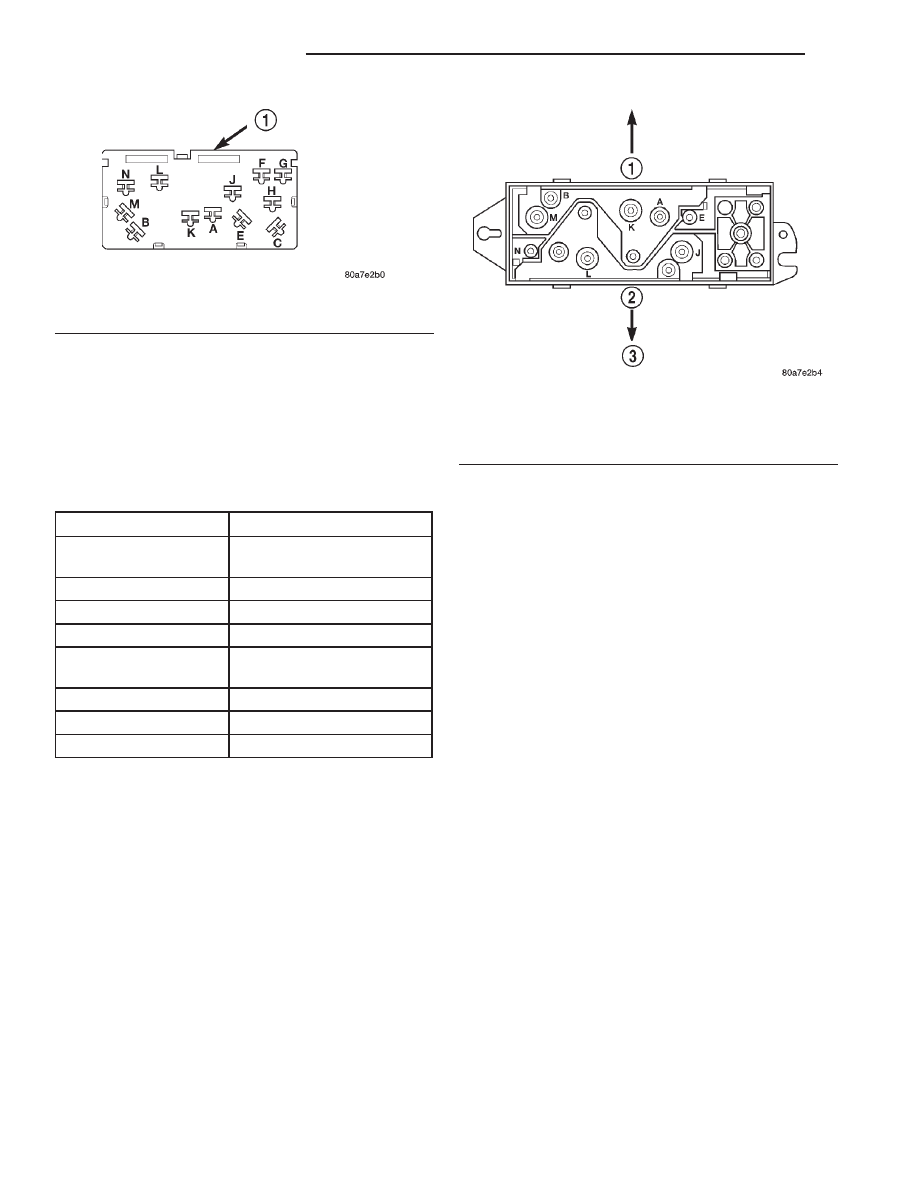
(2) Using an ohmmeter, perform the Switch Conti-
nuity Tests below and refer to (Fig. 2) for Pin loca-
tions. If there is no continuity at any of the switch
positions, replace switch.
VOLTAGE
The following test will determine whether or not
voltage is continuous through the body harness to
the switch.
(1) Remove power seat switch from mounting posi-
tion and disconnect switch from wiring harness.
(2) Using a voltmeter, connect the ground lead to
Pin 5 of the switch harness connector. Connect the
positive lead to Pin 1. If battery voltage the ground
and B+ circuit is OK. If no voltage check circuit
breaker and repair as necessary.
REMOVAL AND INSTALLATION
FRONT SEAT ASSEMBLY
Refer to Group 23, Body for Front Seat Removal
and Installation.
POWER FRONT SEAT ADJUSTER
REMOVAL
(1) Disconnect and isolate the battery negative
remote cable (Fig. 3).
(2) Remove Front Seat Assembly from vehicle.
Refer to Group 23 Body, for Removal and Installa-
tion.
(3) Remove Front Seat Back. Refer to Group 23
Body for Removal and Installation
(4) Separate power seat switch and harness from
seat adjuster.
(5) Remove four power seat adjuster mounting
screws from cushion pan and remove from seat
assembly.
INSTALLATION
For installation, reverse the above procedures.
Fig. 1 Seat Motor Switch Connector
1 – BLACK
SEAT SWITCH CONTINUITY TEST
SWITCH POSITION
CONTINUITY BETWEEN
OFF
B-N, B-J, B-M, B-E, B-K,
B-L
VERTICAL UP
B-M, B-E, A-N, A-J
VERTICAL DOWN
B-N, B-J, A-M, A-E
HORIZONTAL AFT
B-K, A-L
HORIZONTAL
FORWARD
B-L, S-K
FRONT TILT UP
S-J, B-E
FRONT TILT DOWN
A-E, B-J
REAR TILT UP
A-N, B-N
Fig. 2 Power Seat Switch
1 – UP
2 – DOWN
3 – TERMINALS SHOWN AS VIEWED FROM REAR OF SWITCH
8R - 2
POWER SEAT SYSTEMS
JX
DIAGNOSIS AND TESTING (Continued)
Нет комментариевНе стесняйтесь поделиться с нами вашим ценным мнением.
Текст