
Chrysler Stratus Convertible. Manual — part 179
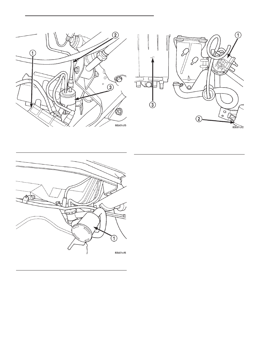
(12) Remove push pin from bracket for EVAP can-
ister (Fig. 27). Remove canister.
INSTALLATION
(1) Install EVAP canister to bracket install push
pin.
(2) Install hoses and lines.
(3) Raise the fuel tank on the transmission stand.
(4) Connect the purge and vent lines.
(5) Connect LDP and fuel pump electrical connec-
tor.
(6) Raise tank into position and install tank
straps.
(7) Install the fuel filler tube and tighten the
clamp.
(8) Lower vehicle.
(9) Connect the battery cable.
(10) Fill fuel tank. Use the DRB scan tool to pres-
surize the fuel system. Check for leaks.
PROPORTIONAL PURGE SOLENOID
REMOVAL
(1) Remove the negative battery cable.
(2) Remove solenoid from bracket by pulling up on
solenoid.
(3) Disconnect electrical connector from solenoid.
(4) Disconnect vacuum tubes from solenoid.
INSTALLATION
The top of the solenoid has TOP printed on it. The
solenoid will not operate unless it is installed cor-
rectly.
(1) Connect vacuum tube to solenoid.
(2) Connect electrical connector to solenoid.
(3) Install solenoid on bracket.
(4) Install the negative battery cable.
Fig. 25 Fuel Line
1 – FUEL PUMP MODULE
2 – FUEL LINE
3 – FUEL FILTER
Fig. 26 Evap Components
1 – LDP FILTER
Fig. 27 LDP and EVAP Canister
1 – LDP
2 – LDP FILTER
3 – EVAP CANISTER
JX
EMISSION CONTROL SYSTEMS
25 - 35
REMOVAL AND INSTALLATION (Continued)
EXHAUST GAS RECIRCULATION (EGR) SYSTEM
TABLE OF CONTENTS
page
page
DESCRIPTION AND OPERATION
EXHAUST GAS RECIRCULATION (EGR)
SYSTEM . . . . . . . . . . . . . . . . . . . . . . . . . . . . . . 36
REMOVAL AND INSTALLATION
EGR VALVE AND TRANSDUCER—2.0L . . . . . . . . 37
EGR TUBE—2.0L . . . . . . . . . . . . . . . . . . . . . . . . . 38
SPECIFICATIONS
TORQUE . . . . . . . . . . . . . . . . . . . . . . . . . . . . . . . 38
DESCRIPTION AND OPERATION
EXHAUST GAS RECIRCULATION (EGR)
SYSTEM
DESCRIPTION
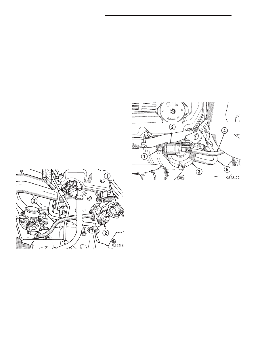
The EGR system consists of (Fig. 1), (Fig. 2), and
(Fig. 3) :
• EGR tube
• EGR valve
• Electric EGR Transducer
• Connecting hoses
OPERATION
Refer to Monitored Systems - EGR Monitor in this
group for more information.
The EGR system reduces oxides of nitrogen (NOx)
in engine exhaust and helps prevent detonation
(engine knock). Under normal operating conditions,
engine cylinder temperature can reach more than
3000°F. Formation of NOx increases proportionally
with combustion temperature. To reduce the emission
of these oxides, the cylinder temperature must be
lowered. The system allows a predetermined amount
of hot exhaust gas to recirculate and dilute the
incoming air/fuel mixture. The diluted air/fuel mix-
ture reduces peak flame temperature during combus-
tion.
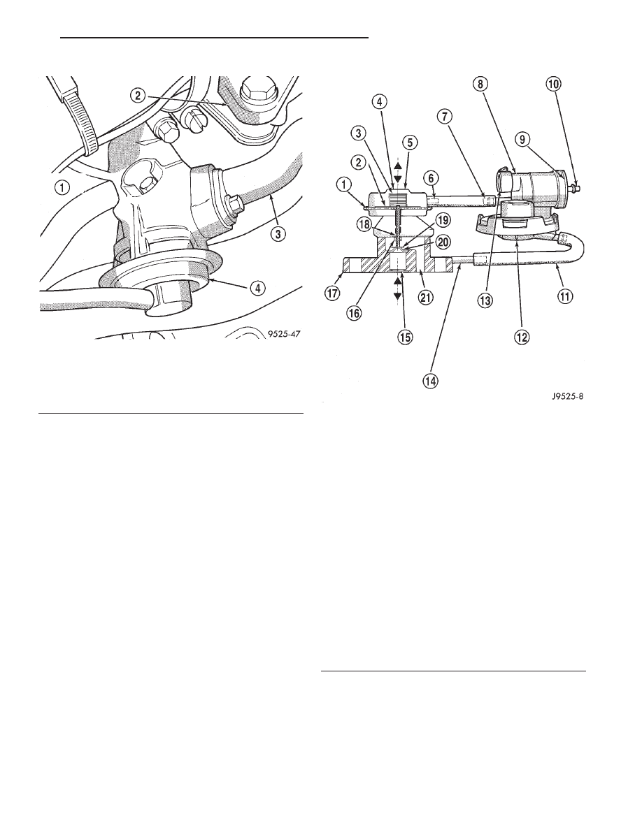
The electric EGR transducer contains an electri-
cally operated solenoid and a back-pressure trans-
ducer (Fig. 4). The Powertrain Control Module (PCM)
operates the solenoid. The PCM determines when to
energize the solenoid. Exhaust system back-pressure
controls the transducer.
When the PCM energizes the solenoid, vacuum
does not reach the transducer. Vacuum flows to the
transducer when the PCM de-energizes the solenoid.
When exhaust system back-pressure becomes high
enough, it fully closes a bleed valve in the trans-
ducer. When the PCM de-energizes the solenoid and
back-pressure closes the transducer bleed valve, vac-
Fig. 1 EGR System—2.4L
1 – EGR SOLENOID AND TRANSDUCER
2 – EGR VALVE
3 – EGR TUBE
Fig. 2 EGR Control Valve—2.5L
1 – VACUUM INLET
2 – EGR SOLENOID
3 – EGR BACK PRESSURE TRANSDUCER
4 – VACUUM OUTLET TO EGR VALVE
5 – BACK PRESSURE HOSE
25 - 36
EMISSION CONTROL SYSTEMS
JX
uum flows through the transducer to operate the
EGR valve.
De-energizing the solenoid, but not fully closing the
transducer bleed hole (because of low back-pressure),
varies the strength of vacuum applied to the EGR
valve. Varying the strength of the vacuum changes
the amount of EGR supplied to the engine. This pro-
vides the correct amount of exhaust gas recirculation
for different operating conditions.
This system does not allow EGR at idle.
A failed or malfunctioning EGR system can cause
engine spark knock, sags or hesitation, rough idle,
engine stalling and increased emissions.
REMOVAL AND INSTALLATION
EGR VALVE AND TRANSDUCER—2.0L
If the EGR system operates incorrectly, replace the
entire EGR valve and transducer together. The EGR
valve
and
electrical
transducer
are
calibrated
together.
REMOVAL
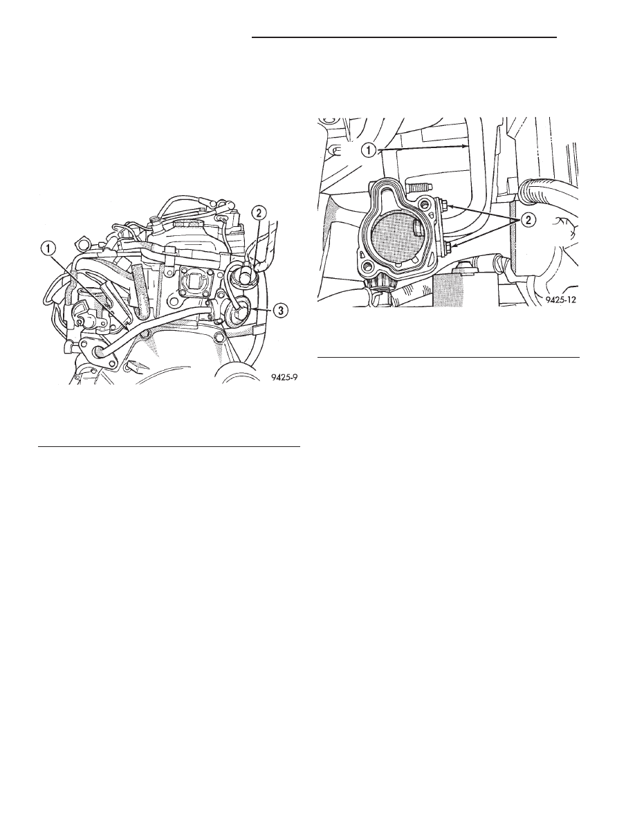
The EGR valve and EGR transducer attach to the
rear of the cylinder head (Fig. 5).
(1) Disconnect vacuum supply tube from EGR
transducer solenoid.
(2) Disconnect electrical connector from solenoid.
(3) Remove EGR tube to EGR valve screws.
(4) Remove EGR valve mounting screws. Remove
EGR valve and transducer.
(5) Clean gasket surfaces. Discard old gaskets. If
necessary, clean EGR passages.
Fig. 3 EGR Valve—2.5L
1 – EGR VALVE SCREW (2)
2 – THERMOSTAT HOUSING
3 – EGR TUBE
4 – EGR VALVE
Fig. 4 Electric EGR Transducer
1 – DIAPHRAGM
2 – PISTON
3 – SPRING
4 – EGR VALVE ASSEMBLY
5 – VACUUM MOTOR
6 – VACUUM MOTOR FITTING
7 – VACUUM OUTLET FITTING TO EGR VALVE
8 – EGR VALVE CONTROL ASSEMBLY
9 – ELECTRIC SOLENOID PORTION OF VALVE CONTROL
10 – VACUUM INLET FITTING FROM ENGINE
11 – BACK-PRESSURE HOSE
12 – TRANSDUCER PORTION OF VALVE CONTROL
13 – ELECTRICAL CONNECTION POINT
14 – EGR VALVE BACK-PRESSURE FITTING
15 – EXHAUST GAS INLET
16 – STEM PROTECTOR AND BUSHING
17 – BASE
18 – MOVEMENT INDICATOR
19 – POPPET VALVE
20 – SEAT
21 – EXHAUST GAS OUTLET
JX
EMISSION CONTROL SYSTEMS
25 - 37
DESCRIPTION AND OPERATION (Continued)
INSTALLATION
(1) Loosely install EGR valve with new gaskets.
(2) Finger tighten EGR tube fasteners.
(3) Tighten EGR valve mounting screws to 22 N·m
(200 in. lbs.) torque.
(4) Tighten EGR tube fasteners to 11 N·m (95 in.
lbs.) torque.
(5) Connect vacuum supply tube to solenoid.
(6) Attach electrical connector to solenoid.
EGR TUBE—2.0L
The EGR tube attaches to the intake manifold ple-
num below the throttle body and EGR valve.
REMOVAL
(1) Remove screws attaching EGR tube to intake
manifold (Fig. 6).
(2) Remove EGR tube to EGR valve screws.
(3) Remove EGR tube. Clean gasket surface on the
EGR valve. Wipe clean the grommet on the intake
manifold.
INSTALLATION
The rubber grommet that seals the EGR tube to
intake manifold connection is reusable. Use a new
gasket on the EGR tube to EGR valve connection.
(1) Loosely install the EGR tube and fasteners.
(2) Loose install EGR tube to the EGR valve and
intake manifold.
(3) Tighten the EGR tube to intake manifold ple-
num screws to 11 N·m (95 in. lbs) torque.
(4) Tighten the EGR tube to EGR valve screws to
11 N·m (95 in. lbs.) torque.
SPECIFICATIONS
TORQUE
Description
Torque
EGR valve to cyl. head . . . . . . 22 N·m (195 in. lbs.)
EGR tube to EGR valve . . . . . . 11 N·m (97 in. lbs.)
Fig. 5 EGR System
1 – EGR TUBE
2 – ELECTRICAL EGR TRANSDUCER
3 – EGR VALVE
Fig. 6 EGR Tube Stud Bolts
1 – EGR TUBE
2 – EGR TUBE MOUNTING SCREWS
25 - 38
EMISSION CONTROL SYSTEMS
JX
REMOVAL AND INSTALLATION (Continued)
Нет комментариевНе стесняйтесь поделиться с нами вашим ценным мнением.
Текст