
Chrysler Stratus Convertible. Manual — part 19
OPERATION
At above idle conditions, air flow through the
throttle body is controlled by a cable operated throt-
tle blade. During closed throttle idle conditions, the
idle air control motor controls air flow. Refer to Idle
Air Control Motor in this section.
REMOVAL AND INSTALLATION
THROTTLE BODY—2.5L ENGINE
REMOVAL
(1) Remove the negative battery cable.
(2) Remove air tube from throttle body.
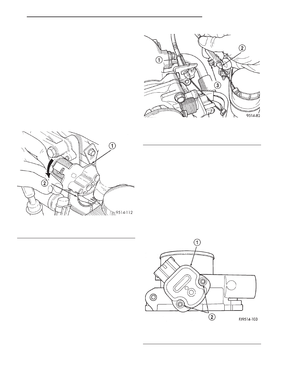
(3) Remove throttle cable from the throttle body
lever (Fig. 20).
(4) Push release tang toward dash panel on throt-
tle cable and slide cable out of bracket (Fig. 21).
(5) Slide speed control cable out of bracket, if
equipped (Fig. 21).
(6) Remove EVAP purge hose from nipple on throt-
tle body.
(7) Remove connectors from throttle position sen-
sor and idle air control motor.
(8) Remove bolts holding throttle body to intake
manifold. Remove throttle body.
INSTALLATION
(1) Attach electrical connectors to idle air control
motor and throttle position sensor.
(2) Install new gasket.
(3) Position throttle body on intake and install mount-
ing bolts. Tighten bolts to 28.25 N·m (250 in. lbs.).
(4) Install speed control cable (if equipped) and
throttle cable into throttle lever.
(5) Install cables into cable bracket.
(6) Install air inlet tube. Tighten clamps to 3
6.5
N·m (25
65 in. lbs.) torque.
(7) Install the negative battery cable.
THROTTLE POSITION SENSOR (TPS)—2.5L
The TPS attaches to the side of the throttle body
(Fig. 22).
REMOVAL
(1) Remove the negative battery cable.
(2) Remove throttle body. Refer to Throttle Body in
this section.
(3) Remove TPS mounting screws.
(4) Remove throttle position sensor.
Fig. 20 Throttle Cable Attachment to Throttle Body
1 – THROTTLE LEVER
2 – THROTTLE CABLE
Fig. 21 Throttle Cable Attachment
1 – SPEED CONTROL CABLE
2 – THROTTLE CABLE
3 – RELEASE TANG
Fig. 22 Throttle Position Sensor—2.5L Engine
1 – THROTTLE POSITION SENSOR
2 – RETAINING SCREWS
JX
FUEL SYSTEM
14 - 35
DESCRIPTION AND OPERATION (Continued)
INSTALLATION
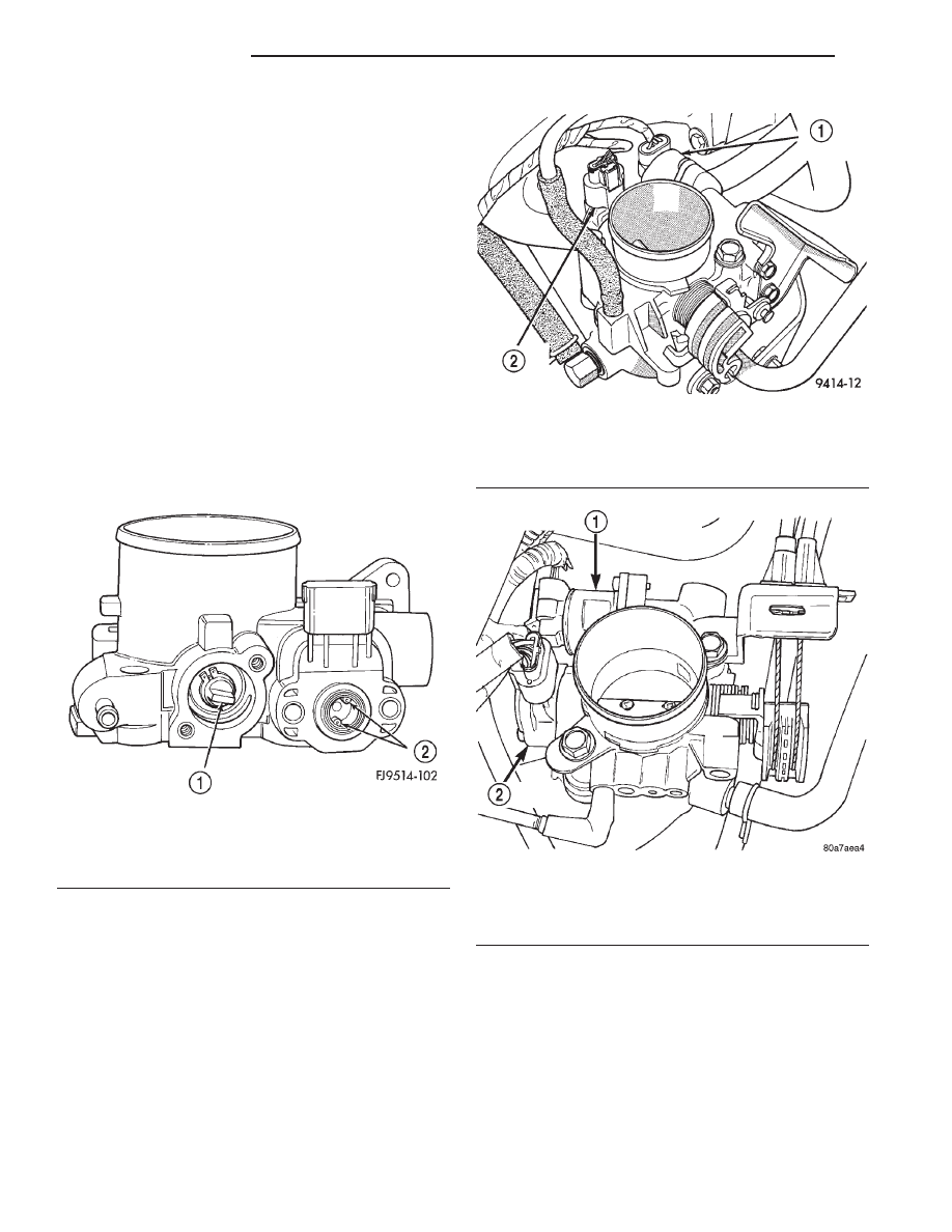
(1) The throttle shaft end of the throttle body
slides into a socket in the TPS (Fig. 23). The socket
has two tabs inside it. The throttle shaft rests
against the tabs. When indexed correctly, the TPS
can rotate a few degrees to line up the mounting
screw holes with the screw holes in the throttle body.
The TPS has slight tension when rotated into posi-
tion. If it is difficult to rotate the TPS into position,
reinstall the sensor with the throttle shaft on the
other side of the tabs in the socket of the TPS.
Tighten mounting screws to 6.2 N·m (55 in. lbs.)
torque.
(2) After installing the TPS, the throttle plate
should be closed. If the throttle plate is open, install
the sensor on the other side of the tabs in the socket.
(3) Attach electrical connectors to idle air control
motor and throttle position sensor.
(4) Install throttle body to intake manifold. Refer
to throttle body in this section.
(5) Install the negative battery cable.
IDLE AIR CONTROL MOTOR—2.0/2.4/2.5L
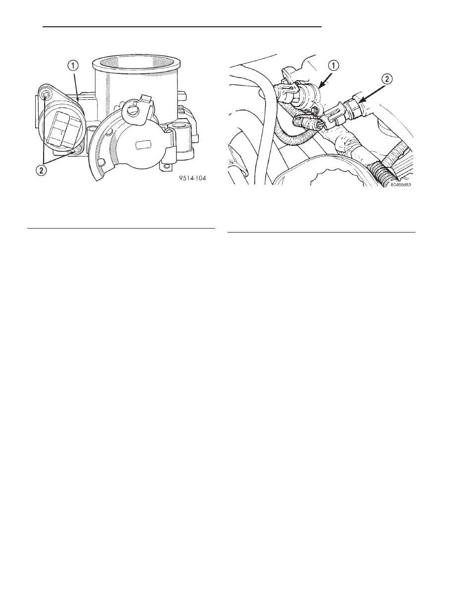
The idle air control motor attaches to the side of
the throttle body (Fig. 24) or (Fig. 25) or (Fig. 26).
REMOVAL
(1) Remove throttle body. Refer to Throttle Body in
this section.
(2) Disconnect electrical connector from idle air
control motor and throttle position sensor.
(3) Remove idle air control motor mounting screws.
(4) Remove idle air control motor. Ensure O-ring is
removed with the motor.
INSTALLATION
(1) The new idle air control motor has a new
O-ring installed on it. If pintle measures more than 1
inch (25 mm) it must be retracted. Use the DRB AIS
Motor Open/Close Test to retract the pintle (battery
must be connected.)
(2) Carefully place idle air control motor into
throttle body.
Fig. 23 Indexing Throttle Position Sensor—2.5L
Engine
1 – THROTTLE SHAFT
2 – TABS
Fig. 24 Throttle Position Sensor and Idle Air Control
Motor—2.0L
1 – IDLE AIR CONTROL MOTOR
2 – THROTTLE POSITION SENSOR
Fig. 25 Throttle Position Sensor and Idle Air Control
Motor—2.4L
1 – IDLE AIR CONTROL MOTOR
2 – TPS
14 - 36
FUEL SYSTEM
JX
REMOVAL AND INSTALLATION (Continued)
(3) Install mounting screws. Tighten screws to:
2.0L = 5.3 N·m (45 in. lbs.) 2.4/2.5L = 6.2 N·m (55 in.
lbs.) torque.
(4) Attach electrical connectors to idle air control
motor and throttle position sensor.
(5) Install throttle body. Refer to Throttle Body in
this section.
INTAKE AIR TEMPERATURE SENSOR—2.5L
The intake air temperature sensor threads into the
intake manifold plenum (Fig. 27).
REMOVAL
(1) Remove the negative battery cable.
(2) Disconnect electrical connector from sensor.
(3) Remove sensor.
INSTALLATION
(1) Install sensor. Tighten sensor to 12
6 1 N·m
(9
6 1 ft. lbs.) torque.
(2) Attach electrical connector to sensor.
(3) Install the negative battery cable.
MANIFOLD ABSOLUTE PRESSURE (MAP)
SENSOR
The MAP sensor attaches to the intake manifold
plenum (Fig. 27).
REMOVAL
(1) Remove the negative battery cable.
(2) Disconnect electrical connector from MAP sensor.
(3) Remove sensor mounting screws.
(4) Remove sensor.
INSTALLATION
(1) Insert sensor into intake manifold while mak-
ing sure not to damage O-ring seal.
(2) Tighten mounting screws to 3.4 N·m (30 in. lbs)
torque.
(3) Attach electrical connector to sensor.
(4) Install the negative battery cable.
POWERTRAIN CONTROL MODULE
The PCM engine control strategy prevents reduced
idle speeds until after the engine operates for 320 km
(200 miles). If the PCM is replaced after 320 km (200
miles) of usage, update the mileage and vehicle iden-
tification number (VIN) in the new PCM. Use the
DRB scan tool to change the millage and VIN in the
PCM. If this step is not done a Diagnostic Trouble
Code (DTC) may be set. Refer to the appropriate
Powertrain Diagnostic Manual and the DRB scan
tool.
The PCM attaches to a bracket between the air
cleaner housing and Power Distribution Center
(PDC).
REMOVAL
(1) Disconnect
negative
cable
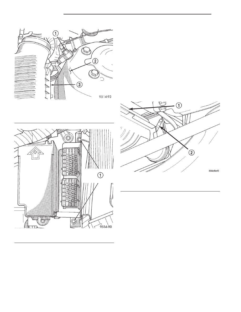
from
auxiliary
jumper terminal (Fig. 28).
(2) Disconnect both 40-way connectors from PCM.
(3) Remove screws attaching PCM to bracket (Fig.
29).
(4) Lift PCM up to remove it from vehicle.
INSTALLATION
(1) Install PCM. Tighten mounting screws.
(2) Attach both 40-way connectors to PCM.
Fig. 26 Throttle Position Sensor and Idle Air Control
Motor—2.5L
1 – IDLE AIR CONTROL MOTOR
2 – RETAINER SCREWS
Fig. 27 Intake Air Temperature Sensor and MAP
Sensor—2.5L
1 – MAP SENSOR
2 – INTAKE AIR TEMPERATURE SENSOR
JX
FUEL SYSTEM
14 - 37
REMOVAL AND INSTALLATION (Continued)
(3) Connect negative cable to auxiliary jumper ter-
minal.
OXYGEN SENSOR 1/1 UPSTREAM—2.5L
REMOVAL
(1) Remove the negative battery cable.
(2) Raise and support vehicle.
(3) Disconnect electrical connector from sensor.
(4) Remove sensor using an oxygen sensor crow
foot wrench such as Snap-On tool YA8875 or equiva-
lent (Fig. 30).
INSTALLATION
(1) After removing the sensor, the exhaust mani-
fold threads must be cleaned with an 18 mm X 1.5 +
6E tap. If reusing the original sensor, coat the sensor
threads with an anti-seize compound such as Loctite
t
771-64 or equivalent. New sensors have compound on
the threads and do not require an additional coating.
Tighten the sensor to 28 N·m (20 ft. lbs.) torque.
(2) Connect electrical connector to sensor.
(3) Lower vehicle.
(4) Install the negative battery cable.
OXYGEN SENSOR 1/2 DOWNSTREAM
The downstream heated oxygen sensor threads into
the exhaust pipe behind the catalytic convertor.
REMOVAL
(1) Remove the negative battery cable.
(2) Raise vehicle.
(3) Disconnect electrical connector from sensor.
(4) Disconnect sensor electrical harness from clips
along body.
(5) Remove sensor using an oxygen sensor crow
foot wrench such as Snap-On tool YA8875 or equiva-
lent (Fig. 31).
INSTALLATION
(1) After removing the sensor, the exhaust mani-
fold threads must be cleaned with an 18 mm X 1.5 +
6E tap. If reusing the original sensor, coat the sensor
threads with an anti-seize compound such as Loctite
t
771-64 or equivalent. New sensors have compound on
Fig. 28 Auxiliary Jumper Terminal
1 – AUXILIARY JUMPER TERMINAL
2 – LEFT STRUT TOWER
3 – AIR CLEANER HOUSING
Fig. 29 PCM Bracket Screws
1 – POWERTRAIN CONTROL MODULE BRACKET SCREWS
Fig. 30 Oxygen Sensor 1/1 Upstream
1 – CATALYTIC CONVERTOR
2 – UPSTREAM HEATED OXYGEN SENSOR
14 - 38
FUEL SYSTEM
JX
REMOVAL AND INSTALLATION (Continued)
Нет комментариевНе стесняйтесь поделиться с нами вашим ценным мнением.
Текст