
Chrysler Stratus Convertible. Manual — part 184
SPECIFICATIONS
TORQUE SPECIFICATIONS
DESCRIPTION
TORQUE
Caliper To Knuckle Bolts . . . . . 31 N·m (23 ft. lbs.)
Driveshaft Nut . . . . . . . . . . . 142 N·m (105 ft. lbs.)
Front Wheel Lug Nuts . . . . . . 135 N·m (100 ft. lbs.)
Knuckle To Ball Stud Nut . . . . . 95 N·m (70 ft. lbs.)
Tie Rod End To Knuckle . . . . . . 61 N·m (45 ft. lbs.)
SPECIAL TOOLS
DRIVESHAFT
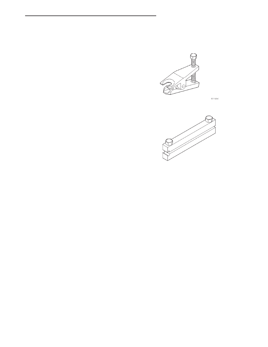
Tie Rod Remover MB-991113
Boot Clamp Installer C-4975A
JX
DIFFERENTIAL AND DRIVELINE
3 - 17
BRAKES
TABLE OF CONTENTS
page
page
BASE BRAKE SYSTEM . . . . . . . . . . . . . . . . . . . . . . 1
ANTILOCK BRAKE SYSTEM . . . . . . . . . . . . . . . . . 75
BASE BRAKE SYSTEM
TABLE OF CONTENTS
page
page
DESCRIPTION AND OPERATION
BASE BRAKE SYSTEM . . . . . . . . . . . . . . . . . . . . . 2
BRAKE PEDAL . . . . . . . . . . . . . . . . . . . . . . . . . . . 2
MASTER CYLINDER . . . . . . . . . . . . . . . . . . . . . . . 2
POWER BRAKE BOOSTER . . . . . . . . . . . . . . . . . . 4
BRAKE TUBES AND HOSES . . . . . . . . . . . . . . . . . 5
PROPORTIONING VALVE . . . . . . . . . . . . . . . . . . . 5
DISC BRAKES (FRONT) . . . . . . . . . . . . . . . . . . . . 6
DISC BRAKES (REAR). . . . . . . . . . . . . . . . . . . . . . 7
DRUM BRAKES (REAR). . . . . . . . . . . . . . . . . . . . . 8
PARKING BRAKES . . . . . . . . . . . . . . . . . . . . . . . . 8
BRAKE LAMP SWITCH . . . . . . . . . . . . . . . . . . . . . 9
BRAKE FLUID LEVEL SWITCH . . . . . . . . . . . . . . 10
RED BRAKE WARNING LAMP . . . . . . . . . . . . . . . 10
DIAGNOSIS AND TESTING
BASE BRAKE SYSTEM DIAGNOSIS CHARTS . . . 10
POWER BRAKE BOOSTER . . . . . . . . . . . . . . . . . 13
PROPORTIONING VALVE . . . . . . . . . . . . . . . . . . 14
BRAKE ROTOR . . . . . . . . . . . . . . . . . . . . . . . . . . 16
BRAKE DRUM . . . . . . . . . . . . . . . . . . . . . . . . . . . 18
DRUM BRAKE AUTOMATIC ADJUSTER. . . . . . . . 19
BRAKE FLUID CONTAMINATION . . . . . . . . . . . . . 19
BRAKE LAMP SWITCH . . . . . . . . . . . . . . . . . . . . 20
SERVICE PROCEDURES
BRAKE FLUID LEVEL CHECKING . . . . . . . . . . . . 20
BASE BRAKE BLEEDING. . . . . . . . . . . . . . . . . . . 20
MASTER CYLINDER BLEEDING . . . . . . . . . . . . . 21
BRAKE TUBE REPAIR . . . . . . . . . . . . . . . . . . . . . 22
BRAKE ROTOR MACHINING . . . . . . . . . . . . . . . . 23
BRAKE DRUM MACHINING . . . . . . . . . . . . . . . . . 24
REMOVAL AND INSTALLATION
SERVICE WARNINGS AND CAUTIONS . . . . . . . . 25
BRAKE PEDAL. . . . . . . . . . . . . . . . . . . . . . . . . . . 25
MASTER CYLINDER . . . . . . . . . . . . . . . . . . . . . . 27
BRAKE FLUID LEVEL SWITCH . . . . . . . . . . . . . . 29
POWER BRAKE BOOSTER (2.5L ENGINE) . . . . . 30
BRAKE TUBES AND HOSES . . . . . . . . . . . . . . . . 35
PROPORTIONING VALVE . . . . . . . . . . . . . . . . . . 35
DISC BRAKE CALIPER (FRONT) . . . . . . . . . . . . . 36
DISC BRAKE SHOES (FRONT) . . . . . . . . . . . . . . 37
DISC BRAKE CALIPER (REAR) . . . . . . . . . . . . . . 40
DISC BRAKE SHOES (REAR) . . . . . . . . . . . . . . . 41
DRUM BRAKE WHEEL CYLINDER (REAR) . . . . . 44
DRUM BRAKE SHOES (REAR) . . . . . . . . . . . . . . 45
BRAKE DRUM . . . . . . . . . . . . . . . . . . . . . . . . . . . 48
DRUM BRAKE SUPPORT PLATE (REAR) . . . . . . 49
PARKING BRAKE LEVER. . . . . . . . . . . . . . . . . . . 51
PARKING BRAKE CABLE (REAR) . . . . . . . . . . . . 55
PARKING BRAKE SHOES
(WITH REAR DISC BRAKES) . . . . . . . . . . . . . . 61
BRAKE LAMP SWITCH . . . . . . . . . . . . . . . . . . . . 62
DISASSEMBLY AND ASSEMBLY
RESERVOIR . . . . . . . . . . . . . . . . . . . . . . . . . . . 63
DISC BRAKE CALIPER (FRONT AND REAR) . . . . 64
DRUM BRAKE WHEEL CYLINDER (REAR) . . . . . 69
CLEANING AND INSPECTION
DISC BRAKES (FRONT). . . . . . . . . . . . . . . . . . . . 70
DISC BRAKES (REAR). . . . . . . . . . . . . . . . . . . . . 70
DRUM BRAKES (REAR). . . . . . . . . . . . . . . . . . . . 70
BRAKE TUBES AND HOSES . . . . . . . . . . . . . . . . 71
ADJUSTMENTS
DRUM BRAKE SHOES. . . . . . . . . . . . . . . . . . . . . 71
PARKING BRAKE. . . . . . . . . . . . . . . . . . . . . . . . . 72
BRAKE LAMP SWITCH . . . . . . . . . . . . . . . . . . . . 72
SPECIFICATIONS
SPECIFICATIONS . . . . . . . . . . . . . . . . . . . . . . . 73
SPECIAL TOOLS
BASE BRAKE SYSTEM . . . . . . . . . . . . . . . . . . . . 74
JX
BRAKES
5 - 1
DESCRIPTION AND OPERATION
BASE BRAKE SYSTEM
DESCRIPTION
The base brake system consists of the following
components:
• Brake pedal
• power brake booster
• brake tubes and hoses
• proportioning valves
• disc brakes
• drum brakes
• brake lamp switch
• brake fluid level switch
• parking brakes
Front disc brakes control the braking of the front
wheels; rear braking is controlled by rear drum
brakes as standard equipment. Rear disc brakes are
optional.
The hydraulic brake system is diagonally split on
both the non-antilock and antilock braking systems.
This means the left front and right rear brakes are
on one hydraulic circuit and the right front and left
rear are on the other.
Vehicles equipped with the optional antilock brake
system (ABS) use a system designated Mark 20i.
This system shares most base brake hardware used
on vehicles without ABS. A vehicle equipped with
ABS, however, uses a different power brake booster,
master cylinder, and brake tubes. Also included in
the ABS system is an integrated control unit (ICU),
four wheel speed sensors, and an electronic controller
referred to as the controller antilock brake (CAB).
These components are described in detail in the
ANTILOCK BRAKE SYSTEM section in this group
of the service manual.
OPERATION
When a vehicle needs to be stopped, the driver
applies the brake pedal. The brake pedal pushes the
input rod of the power brake booster into the booster.
The booster uses vacuum to ease pedal effort as force
is transferred through the booster to the master cyl-
inder. The booster’s output rod pushes in the master
cylinder’s primary and secondary pistons applying
hydraulic pressure through the chassis brake tubes
and proportioning valves to the brakes at each tire
and wheel assembly.
The
parking
brake
is
hand-operated.
When
applied, the parking brake lever pulls on cables that
actuate brake shoes at each rear wheel.
BRAKE PEDAL
DESCRIPTION
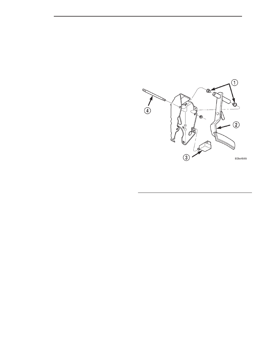
A suspended type brake pedal is used on this vehi-
cle (Fig. 1). The pedal pivots on a shaft mounted in
the pedal support bracket under the instrument
panel. The pedal also connects to the power brake
booster input rod.
OPERATION
When the brake pedal is depressed, it pushes in on
the power brake booster input rod applying the
brakes. At the same time, it allows the brake lamp
switch’s plunger to extend, thus applying the brake
lamps.
MASTER CYLINDER
DESCRIPTION
This vehicle uses 2 differently designed master cyl-
inder assemblies depending on whether the vehicle is
or is not equipped with antilock brakes.
Vehicles not equipped with ABS use a standard
compensating port master cylinder design, while
vehicles equipped with ABS use a center valve design
master cylinder.
On vehicles equipped with ABS brakes, the master
cylinder is a two outlet design. On vehicles not
equipped with ABS brakes, the master cylinder is a 4
outlet design. All vehicles are equipped with a mas-
ter cylinder having a bore diameter of 22.2 mm.
Fig. 1 Brake Pedal
1 – BUSHINGS
2 – BRAKE PEDAL
3 – BRAKE LAMP SWITCH
4 – PIVOT SHAFT
5 - 2
BRAKES
JX
Нет комментариевНе стесняйтесь поделиться с нами вашим ценным мнением.
Текст