Daewoo Matiz (2003 year). Manual — part 148
ANTILOCK BRAKE SYSTEM 4F – 41
BLANK
4F – 42 ANTILOCK BRAKE SYSTEM
D17E304B
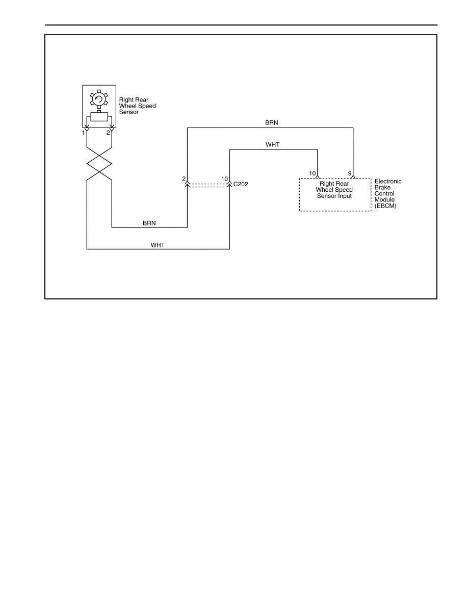
DIAGNOSTIC TROUBLE CODE (DTC) 0504
RIGHT REAR WHEEL SPEED SENSOR CIRCUIT OPEN OR SHORTED
Circuit Description
As a toothed ring passes by the wheel speed sensor,
changes in the electromagnetic field cause the wheel
speed sensor to produce a sinusoidal (AC) voltage sig-
nal whose frequency is proportional to the wheel speed.
The magnitude of this signal is directly related to wheel
speed and the proximity of the wheel speed sensor to
the toothed ring often referred to as the air gap.
Diagnosis
This test detects a short to battery, ground, or open in
the right rear wheel speed sensor circuit.
Cause(s)
D
The wheel speed circuit is open or shorted to the bat-
tery or ground.
D
There is a loose connection in the wheel speed cir-
cuit.
D
The wheel speed sensor resistance is very high.
D
The EBCM is malfunctioning.
Fail Action
This is a critical operational fault. The ABS is disabled
and the ABS warning lamp is turned on. The proportion-
ing is operation.
Diagnostic Aids
An ‘‘intermittent’’ malfunction may be caused by a poor
connection, rubbed through wire insulation, or a wire
that is broken inside the insulation.
Thoroughly check any circuitry suspected of causing the
intermittent complaint. Look for backed out terminals,
improper mating, broken locks, improperly formed or
damaged terminals, poor terminal to wiring connections,
or physical damage to the wiring harness.
Wheel speed sensor resistance will increase as the sen-
sor temperature increases.
When replacing a wheel speed sensor, inspect the sen-
sor terminals and harness connector for corrosion and/
or water intrusion. If evidence of corrosion or water

ANTILOCK BRAKE SYSTEM 4F – 43
intrusion exists, replace the wheel speed sensor har-
ness. If replacing a wheel speed sensor harness, in-
spect the sensor terminals. If you find evidence of
corrosion or water intrusion, replace the wheel speed
sensor. Refer to “Rear Wheel Speed Sensor” in this sec-
tion.
Important: Wheel speed sensor intermittent malfunc-
tions may be difficult to locate. Take care not to disturb
any electrical connections before performing an indi-
cated step of this table. That will ensure that an intermit-
tent connection will not be corrected before the source
of the malfunction is found.
DTC 0504 – Right Rear Wheel Speed Sensor Circuit Open or Shorted
ÑÑÑÑ
ÑÑÑÑ
Step
ÑÑÑÑÑÑÑÑÑÑÑÑÑÑÑÑÑ
ÑÑÑÑÑÑÑÑÑÑÑÑÑÑÑÑÑ
Action
ÑÑÑÑÑ
ÑÑÑÑÑ
Value(s)
ÑÑÑÑÑÑÑ
ÑÑÑÑÑÑÑ
Yes
ÑÑÑÑÑÑ
ÑÑÑÑÑÑ
No
ÑÑÑÑ
ÑÑÑÑ
ÑÑÑÑ
ÑÑÑÑ
ÑÑÑÑ
ÑÑÑÑ
ÑÑÑÑ
ÑÑÑÑ
1
ÑÑÑÑÑÑÑÑÑÑÑÑÑÑÑÑÑ
ÑÑÑÑÑÑÑÑÑÑÑÑÑÑÑÑÑ
ÑÑÑÑÑÑÑÑÑÑÑÑÑÑÑÑÑ
ÑÑÑÑÑÑÑÑÑÑÑÑÑÑÑÑÑ
ÑÑÑÑÑÑÑÑÑÑÑÑÑÑÑÑÑ
ÑÑÑÑÑÑÑÑÑÑÑÑÑÑÑÑÑ
ÑÑÑÑÑÑÑÑÑÑÑÑÑÑÑÑÑ
ÑÑÑÑÑÑÑÑÑÑÑÑÑÑÑÑÑ
1. Turn the ignition switch to OFF.
2. Disconnect the EBCM harness connector from
the EBCM.
3. Use a digital voltmeter (DVM) to measure the
resistance between terminals 9 and 10 of
connector on the EBCM harness.
Is the resistance within the specified value?
ÑÑÑÑÑ
ÑÑÑÑÑ
ÑÑÑÑÑ
ÑÑÑÑÑ
ÑÑÑÑÑ
ÑÑÑÑÑ
ÑÑÑÑÑ
ÑÑÑÑÑ
1.0 k
to
1.5 k
ÑÑÑÑÑÑÑ
ÑÑÑÑÑÑÑ
ÑÑÑÑÑÑÑ
ÑÑÑÑÑÑÑ
ÑÑÑÑÑÑÑ
ÑÑÑÑÑÑÑ
ÑÑÑÑÑÑÑ
ÑÑÑÑÑÑÑ
Go to Step 4
ÑÑÑÑÑÑ
ÑÑÑÑÑÑ
ÑÑÑÑÑÑ
ÑÑÑÑÑÑ
ÑÑÑÑÑÑ
ÑÑÑÑÑÑ
ÑÑÑÑÑÑ
ÑÑÑÑÑÑ
Go to Step 2
ÑÑÑÑ
ÑÑÑÑ
ÑÑÑÑ
ÑÑÑÑ
ÑÑÑÑ
ÑÑÑÑ
2
ÑÑÑÑÑÑÑÑÑÑÑÑÑÑÑÑÑ
ÑÑÑÑÑÑÑÑÑÑÑÑÑÑÑÑÑ
ÑÑÑÑÑÑÑÑÑÑÑÑÑÑÑÑÑ
ÑÑÑÑÑÑÑÑÑÑÑÑÑÑÑÑÑ
ÑÑÑÑÑÑÑÑÑÑÑÑÑÑÑÑÑ
ÑÑÑÑÑÑÑÑÑÑÑÑÑÑÑÑÑ
1. Disconnect the harness from the right rear wheel
speed sensor.
2. Use a DVM to measure the resistance between
terminals 1 and 2 of the right rear wheel speed
sensor connector.
Is the resistance within the specified value?
ÑÑÑÑÑ
ÑÑÑÑÑ
ÑÑÑÑÑ
ÑÑÑÑÑ
ÑÑÑÑÑ
ÑÑÑÑÑ
1.0 k
to
1.5 k
ÑÑÑÑÑÑÑ
ÑÑÑÑÑÑÑ
ÑÑÑÑÑÑÑ
ÑÑÑÑÑÑÑ
ÑÑÑÑÑÑÑ
ÑÑÑÑÑÑÑ
Go to Step 4
ÑÑÑÑÑÑ
ÑÑÑÑÑÑ
ÑÑÑÑÑÑ
ÑÑÑÑÑÑ
ÑÑÑÑÑÑ
ÑÑÑÑÑÑ
Go to Step 3
ÑÑÑÑ
ÑÑÑÑ
ÑÑÑÑ
3
ÑÑÑÑÑÑÑÑÑÑÑÑÑÑÑÑÑ
ÑÑÑÑÑÑÑÑÑÑÑÑÑÑÑÑÑ
ÑÑÑÑÑÑÑÑÑÑÑÑÑÑÑÑÑ
Replace the wheel speed sensor.
Is the repair complete?
ÑÑÑÑÑ
ÑÑÑÑÑ
ÑÑÑÑÑ
–
ÑÑÑÑÑÑÑ
ÑÑÑÑÑÑÑ
ÑÑÑÑÑÑÑ
System OK
ÑÑÑÑÑÑ
ÑÑÑÑÑÑ
ÑÑÑÑÑÑ
–
ÑÑÑÑ
ÑÑÑÑ
ÑÑÑÑ
ÑÑÑÑ
ÑÑÑÑ
ÑÑÑÑ
4
ÑÑÑÑÑÑÑÑÑÑÑÑÑÑÑÑÑ
ÑÑÑÑÑÑÑÑÑÑÑÑÑÑÑÑÑ
ÑÑÑÑÑÑÑÑÑÑÑÑÑÑÑÑÑ
ÑÑÑÑÑÑÑÑÑÑÑÑÑÑÑÑÑ
ÑÑÑÑÑÑÑÑÑÑÑÑÑÑÑÑÑ
ÑÑÑÑÑÑÑÑÑÑÑÑÑÑÑÑÑ
1. Disconnect the connector C202.
2. Use a DVM to measure the resistance between
terminal 2 of the connector C202 and terminal 9
of the EBCM connector.
Does the DVM show the specified value?
ÑÑÑÑÑ
ÑÑÑÑÑ
ÑÑÑÑÑ
ÑÑÑÑÑ
ÑÑÑÑÑ
ÑÑÑÑÑ
less than 1
ÑÑÑÑÑÑÑ
ÑÑÑÑÑÑÑ
ÑÑÑÑÑÑÑ
ÑÑÑÑÑÑÑ
ÑÑÑÑÑÑÑ
ÑÑÑÑÑÑÑ
Go to Step 6
ÑÑÑÑÑÑ
ÑÑÑÑÑÑ
ÑÑÑÑÑÑ
ÑÑÑÑÑÑ
ÑÑÑÑÑÑ
ÑÑÑÑÑÑ
Go to Step 5
ÑÑÑÑ
ÑÑÑÑ
ÑÑÑÑ
ÑÑÑÑ
5
ÑÑÑÑÑÑÑÑÑÑÑÑÑÑÑÑÑ
ÑÑÑÑÑÑÑÑÑÑÑÑÑÑÑÑÑ
ÑÑÑÑÑÑÑÑÑÑÑÑÑÑÑÑÑ
ÑÑÑÑÑÑÑÑÑÑÑÑÑÑÑÑÑ
Repair the high resistance between terminal 2 of the
connector C202 and terminal 9 of the EBCM con-
nector.
Is the repair complete?
ÑÑÑÑÑ
ÑÑÑÑÑ
ÑÑÑÑÑ
ÑÑÑÑÑ
–
ÑÑÑÑÑÑÑ
ÑÑÑÑÑÑÑ
ÑÑÑÑÑÑÑ
ÑÑÑÑÑÑÑ
System OK
ÑÑÑÑÑÑ
ÑÑÑÑÑÑ
ÑÑÑÑÑÑ
ÑÑÑÑÑÑ
–
ÑÑÑÑ
ÑÑÑÑ
ÑÑÑÑ
ÑÑÑÑ
6
ÑÑÑÑÑÑÑÑÑÑÑÑÑÑÑÑÑ
ÑÑÑÑÑÑÑÑÑÑÑÑÑÑÑÑÑ
ÑÑÑÑÑÑÑÑÑÑÑÑÑÑÑÑÑ
ÑÑÑÑÑÑÑÑÑÑÑÑÑÑÑÑÑ
Use a DVM to measure the resistance between ter-
minal 2 of the connector C202 and terminal 2 of the
right rear wheel speed sensor harness connector.
Is the resistance within the specified value?
ÑÑÑÑÑ
ÑÑÑÑÑ
ÑÑÑÑÑ
ÑÑÑÑÑ
less than 1
ÑÑÑÑÑÑÑ
ÑÑÑÑÑÑÑ
ÑÑÑÑÑÑÑ
ÑÑÑÑÑÑÑ
Go to Step 8
ÑÑÑÑÑÑ
ÑÑÑÑÑÑ
ÑÑÑÑÑÑ
ÑÑÑÑÑÑ
Go to Step 7
ÑÑÑÑ
ÑÑÑÑ
ÑÑÑÑ
ÑÑÑÑ
ÑÑÑÑ
7
ÑÑÑÑÑÑÑÑÑÑÑÑÑÑÑÑÑ
ÑÑÑÑÑÑÑÑÑÑÑÑÑÑÑÑÑ
ÑÑÑÑÑÑÑÑÑÑÑÑÑÑÑÑÑ
ÑÑÑÑÑÑÑÑÑÑÑÑÑÑÑÑÑ
ÑÑÑÑÑÑÑÑÑÑÑÑÑÑÑÑÑ
Repair the high resistance between terminal 2 of the
connector C202 and terminal 2 of the right rear
wheel speed sensor harness connector.
Is the repair complete?
ÑÑÑÑÑ
ÑÑÑÑÑ
ÑÑÑÑÑ
ÑÑÑÑÑ
ÑÑÑÑÑ
–
ÑÑÑÑÑÑÑ
ÑÑÑÑÑÑÑ
ÑÑÑÑÑÑÑ
ÑÑÑÑÑÑÑ
ÑÑÑÑÑÑÑ
System OK
ÑÑÑÑÑÑ
ÑÑÑÑÑÑ
ÑÑÑÑÑÑ
ÑÑÑÑÑÑ
ÑÑÑÑÑÑ
–
ÑÑÑÑ
ÑÑÑÑ
ÑÑÑÑ
ÑÑÑÑ
8
ÑÑÑÑÑÑÑÑÑÑÑÑÑÑÑÑÑ
ÑÑÑÑÑÑÑÑÑÑÑÑÑÑÑÑÑ
ÑÑÑÑÑÑÑÑÑÑÑÑÑÑÑÑÑ
ÑÑÑÑÑÑÑÑÑÑÑÑÑÑÑÑÑ
Use a DVM to measure the resistance between ter-
minal 10 of the connector C202 and terminal 10 of
the EBCM connector.
Does the DVM show the specified value?
ÑÑÑÑÑ
ÑÑÑÑÑ
ÑÑÑÑÑ
ÑÑÑÑÑ
less than 1
ÑÑÑÑÑÑÑ
ÑÑÑÑÑÑÑ
ÑÑÑÑÑÑÑ
ÑÑÑÑÑÑÑ
Go to Step 10
ÑÑÑÑÑÑ
ÑÑÑÑÑÑ
ÑÑÑÑÑÑ
ÑÑÑÑÑÑ
Go to Step 9
ÑÑÑÑ
ÑÑÑÑ
ÑÑÑÑ
ÑÑÑÑ
ÑÑÑÑ
9
ÑÑÑÑÑÑÑÑÑÑÑÑÑÑÑÑÑ
ÑÑÑÑÑÑÑÑÑÑÑÑÑÑÑÑÑ
ÑÑÑÑÑÑÑÑÑÑÑÑÑÑÑÑÑ
ÑÑÑÑÑÑÑÑÑÑÑÑÑÑÑÑÑ
ÑÑÑÑÑÑÑÑÑÑÑÑÑÑÑÑÑ
Repair the high resistance between terminal 10 of
the connector C202 and terminal 10 of the EBCM
connector.
Is the repair complete?
ÑÑÑÑÑ
ÑÑÑÑÑ
ÑÑÑÑÑ
ÑÑÑÑÑ
ÑÑÑÑÑ
–
ÑÑÑÑÑÑÑ
ÑÑÑÑÑÑÑ
ÑÑÑÑÑÑÑ
ÑÑÑÑÑÑÑ
ÑÑÑÑÑÑÑ
System OK
ÑÑÑÑÑÑ
ÑÑÑÑÑÑ
ÑÑÑÑÑÑ
ÑÑÑÑÑÑ
ÑÑÑÑÑÑ
–

4F – 44 ANTILOCK BRAKE SYSTEM
DTC 0504 – Right Rear Wheel Speed Sensor Circuit Open or Shorted (Cont’d)
ÑÑÑÑ
ÑÑÑÑ
Step
ÑÑÑÑÑÑÑÑÑÑÑÑÑÑÑÑÑ
ÑÑÑÑÑÑÑÑÑÑÑÑÑÑÑÑÑ
Action
ÑÑÑÑÑ
ÑÑÑÑÑ
Value(s)
ÑÑÑÑÑÑÑ
ÑÑÑÑÑÑÑ
Yes
ÑÑÑÑÑÑ
ÑÑÑÑÑÑ
No
ÑÑÑÑ
ÑÑÑÑ
ÑÑÑÑ
ÑÑÑÑ
10
ÑÑÑÑÑÑÑÑÑÑÑÑÑÑÑÑÑ
ÑÑÑÑÑÑÑÑÑÑÑÑÑÑÑÑÑ
ÑÑÑÑÑÑÑÑÑÑÑÑÑÑÑÑÑ
ÑÑÑÑÑÑÑÑÑÑÑÑÑÑÑÑÑ
Use a DVM to measure the resistance between ter-
minal 10 of the connector C202 and terminal 1 of the
right rear wheel speed sensor harness connector.
Is the resistance within specified value?
ÑÑÑÑÑ
ÑÑÑÑÑ
ÑÑÑÑÑ
ÑÑÑÑÑ
less than 1
ÑÑÑÑÑÑÑ
ÑÑÑÑÑÑÑ
ÑÑÑÑÑÑÑ
ÑÑÑÑÑÑÑ
Go to Step 12
ÑÑÑÑÑÑ
ÑÑÑÑÑÑ
ÑÑÑÑÑÑ
ÑÑÑÑÑÑ
Go to Step 11
ÑÑÑÑ
ÑÑÑÑ
ÑÑÑÑ
ÑÑÑÑ
ÑÑÑÑ
11
ÑÑÑÑÑÑÑÑÑÑÑÑÑÑÑÑÑ
ÑÑÑÑÑÑÑÑÑÑÑÑÑÑÑÑÑ
ÑÑÑÑÑÑÑÑÑÑÑÑÑÑÑÑÑ
ÑÑÑÑÑÑÑÑÑÑÑÑÑÑÑÑÑ
ÑÑÑÑÑÑÑÑÑÑÑÑÑÑÑÑÑ
Repair the high resistance between terminal 10 of
the connector C202 and terminal 1 of the right rear
wheel speed sensor harness connector.
Is the repair complete?
ÑÑÑÑÑ
ÑÑÑÑÑ
ÑÑÑÑÑ
ÑÑÑÑÑ
ÑÑÑÑÑ
–
ÑÑÑÑÑÑÑ
ÑÑÑÑÑÑÑ
ÑÑÑÑÑÑÑ
ÑÑÑÑÑÑÑ
ÑÑÑÑÑÑÑ
System OK
ÑÑÑÑÑÑ
ÑÑÑÑÑÑ
ÑÑÑÑÑÑ
ÑÑÑÑÑÑ
ÑÑÑÑÑÑ
–
ÑÑÑÑ
ÑÑÑÑ
ÑÑÑÑ
12
ÑÑÑÑÑÑÑÑÑÑÑÑÑÑÑÑÑ
ÑÑÑÑÑÑÑÑÑÑÑÑÑÑÑÑÑ
ÑÑÑÑÑÑÑÑÑÑÑÑÑÑÑÑÑ
Use a DVM to measure the resistance between
ground and terminal 9 of the EBCM connector.
Does the DVM show the specified value?
ÑÑÑÑÑ
ÑÑÑÑÑ
ÑÑÑÑÑ
1
ÑÑÑÑÑÑÑ
ÑÑÑÑÑÑÑ
ÑÑÑÑÑÑÑ
Go to Step 14
ÑÑÑÑÑÑ
ÑÑÑÑÑÑ
ÑÑÑÑÑÑ
Go to Step 13
ÑÑÑÑ
ÑÑÑÑ
ÑÑÑÑ
ÑÑÑÑ
ÑÑÑÑ
13
ÑÑÑÑÑÑÑÑÑÑÑÑÑÑÑÑÑ
ÑÑÑÑÑÑÑÑÑÑÑÑÑÑÑÑÑ
ÑÑÑÑÑÑÑÑÑÑÑÑÑÑÑÑÑ
ÑÑÑÑÑÑÑÑÑÑÑÑÑÑÑÑÑ
ÑÑÑÑÑÑÑÑÑÑÑÑÑÑÑÑÑ
Repair the short to ground between terminal 2 of the
connector C202 and terminal 9 of the EBCM con-
nector.
Is the repair complete?
ÑÑÑÑÑ
ÑÑÑÑÑ
ÑÑÑÑÑ
ÑÑÑÑÑ
ÑÑÑÑÑ
–
ÑÑÑÑÑÑÑ
ÑÑÑÑÑÑÑ
ÑÑÑÑÑÑÑ
ÑÑÑÑÑÑÑ
ÑÑÑÑÑÑÑ
System OK
ÑÑÑÑÑÑ
ÑÑÑÑÑÑ
ÑÑÑÑÑÑ
ÑÑÑÑÑÑ
ÑÑÑÑÑÑ
–
ÑÑÑÑ
ÑÑÑÑ
ÑÑÑÑ
14
ÑÑÑÑÑÑÑÑÑÑÑÑÑÑÑÑÑ
ÑÑÑÑÑÑÑÑÑÑÑÑÑÑÑÑÑ
ÑÑÑÑÑÑÑÑÑÑÑÑÑÑÑÑÑ
Use a DVM to measure the resistance between
ground and terminal 2 of the connector C202.
Does the DVM show the specified value?
ÑÑÑÑÑ
ÑÑÑÑÑ
ÑÑÑÑÑ
1
ÑÑÑÑÑÑÑ
ÑÑÑÑÑÑÑ
ÑÑÑÑÑÑÑ
Go to Step 16
ÑÑÑÑÑÑ
ÑÑÑÑÑÑ
ÑÑÑÑÑÑ
Go to Step 15
ÑÑÑÑ
ÑÑÑÑ
ÑÑÑÑ
ÑÑÑÑ
ÑÑÑÑ
15
ÑÑÑÑÑÑÑÑÑÑÑÑÑÑÑÑÑ
ÑÑÑÑÑÑÑÑÑÑÑÑÑÑÑÑÑ
ÑÑÑÑÑÑÑÑÑÑÑÑÑÑÑÑÑ
ÑÑÑÑÑÑÑÑÑÑÑÑÑÑÑÑÑ
ÑÑÑÑÑÑÑÑÑÑÑÑÑÑÑÑÑ
Repair the short to ground between terminal 2 of the
connector C202 and terminal 2 of the right rear
wheel speed sensor harness connector.
Is the repair complete?
ÑÑÑÑÑ
ÑÑÑÑÑ
ÑÑÑÑÑ
ÑÑÑÑÑ
ÑÑÑÑÑ
–
ÑÑÑÑÑÑÑ
ÑÑÑÑÑÑÑ
ÑÑÑÑÑÑÑ
ÑÑÑÑÑÑÑ
ÑÑÑÑÑÑÑ
System OK
ÑÑÑÑÑÑ
ÑÑÑÑÑÑ
ÑÑÑÑÑÑ
ÑÑÑÑÑÑ
ÑÑÑÑÑÑ
–
ÑÑÑÑ
ÑÑÑÑ
ÑÑÑÑ
16
ÑÑÑÑÑÑÑÑÑÑÑÑÑÑÑÑÑ
ÑÑÑÑÑÑÑÑÑÑÑÑÑÑÑÑÑ
ÑÑÑÑÑÑÑÑÑÑÑÑÑÑÑÑÑ
Use a DVM to measure the resistance between
ground and terminal 10 of the EBCM connector.
Does the DVM show the specified value?
ÑÑÑÑÑ
ÑÑÑÑÑ
ÑÑÑÑÑ
1
ÑÑÑÑÑÑÑ
ÑÑÑÑÑÑÑ
ÑÑÑÑÑÑÑ
Go to Step 18
ÑÑÑÑÑÑ
ÑÑÑÑÑÑ
ÑÑÑÑÑÑ
Go to Step 17
ÑÑÑÑ
ÑÑÑÑ
ÑÑÑÑ
ÑÑÑÑ
ÑÑÑÑ
17
ÑÑÑÑÑÑÑÑÑÑÑÑÑÑÑÑÑ
ÑÑÑÑÑÑÑÑÑÑÑÑÑÑÑÑÑ
ÑÑÑÑÑÑÑÑÑÑÑÑÑÑÑÑÑ
ÑÑÑÑÑÑÑÑÑÑÑÑÑÑÑÑÑ
ÑÑÑÑÑÑÑÑÑÑÑÑÑÑÑÑÑ
Repair the short to ground between terminal 10 of
the connector C202 and terminal 10 of the EBCM
connector.
Is the repair complete?
ÑÑÑÑÑ
ÑÑÑÑÑ
ÑÑÑÑÑ
ÑÑÑÑÑ
ÑÑÑÑÑ
–
ÑÑÑÑÑÑÑ
ÑÑÑÑÑÑÑ
ÑÑÑÑÑÑÑ
ÑÑÑÑÑÑÑ
ÑÑÑÑÑÑÑ
System OK
ÑÑÑÑÑÑ
ÑÑÑÑÑÑ
ÑÑÑÑÑÑ
ÑÑÑÑÑÑ
ÑÑÑÑÑÑ
–
ÑÑÑÑ
ÑÑÑÑ
ÑÑÑÑ
18
ÑÑÑÑÑÑÑÑÑÑÑÑÑÑÑÑÑ
ÑÑÑÑÑÑÑÑÑÑÑÑÑÑÑÑÑ
ÑÑÑÑÑÑÑÑÑÑÑÑÑÑÑÑÑ
Use a DVM to measure the resistance between
ground and terminal 10 of the connector C202.
Does the DVM show the specified value?
ÑÑÑÑÑ
ÑÑÑÑÑ
ÑÑÑÑÑ
1
ÑÑÑÑÑÑÑ
ÑÑÑÑÑÑÑ
ÑÑÑÑÑÑÑ
Go to Step 20
ÑÑÑÑÑÑ
ÑÑÑÑÑÑ
ÑÑÑÑÑÑ
Go to Step 19
ÑÑÑÑ
ÑÑÑÑ
ÑÑÑÑ
ÑÑÑÑ
ÑÑÑÑ
19
ÑÑÑÑÑÑÑÑÑÑÑÑÑÑÑÑÑ
ÑÑÑÑÑÑÑÑÑÑÑÑÑÑÑÑÑ
ÑÑÑÑÑÑÑÑÑÑÑÑÑÑÑÑÑ
ÑÑÑÑÑÑÑÑÑÑÑÑÑÑÑÑÑ
ÑÑÑÑÑÑÑÑÑÑÑÑÑÑÑÑÑ
Repair the short to ground between terminal 10 of
the connector C202 and terminal 1 of the right rear
wheel speed sensor harness connector.
Is the repair complete?
ÑÑÑÑÑ
ÑÑÑÑÑ
ÑÑÑÑÑ
ÑÑÑÑÑ
ÑÑÑÑÑ
–
ÑÑÑÑÑÑÑ
ÑÑÑÑÑÑÑ
ÑÑÑÑÑÑÑ
ÑÑÑÑÑÑÑ
ÑÑÑÑÑÑÑ
System OK
ÑÑÑÑÑÑ
ÑÑÑÑÑÑ
ÑÑÑÑÑÑ
ÑÑÑÑÑÑ
ÑÑÑÑÑÑ
–
ÑÑÑÑ
ÑÑÑÑ
ÑÑÑÑ
ÑÑÑÑ
20
ÑÑÑÑÑÑÑÑÑÑÑÑÑÑÑÑÑ
ÑÑÑÑÑÑÑÑÑÑÑÑÑÑÑÑÑ
ÑÑÑÑÑÑÑÑÑÑÑÑÑÑÑÑÑ
ÑÑÑÑÑÑÑÑÑÑÑÑÑÑÑÑÑ
1. Turn the ignition switch to ON.
2. Use a DVM to measure the voltage between
ground and terminal 9 of the EBCM connector.
Is the voltage within the specified value?
ÑÑÑÑÑ
ÑÑÑÑÑ
ÑÑÑÑÑ
ÑÑÑÑÑ
0 v
ÑÑÑÑÑÑÑ
ÑÑÑÑÑÑÑ
ÑÑÑÑÑÑÑ
ÑÑÑÑÑÑÑ
Go to Step 22
ÑÑÑÑÑÑ
ÑÑÑÑÑÑ
ÑÑÑÑÑÑ
ÑÑÑÑÑÑ
Go to Step 21
ÑÑÑÑ
ÑÑÑÑ
ÑÑÑÑ
ÑÑÑÑ
ÑÑÑÑ
21
ÑÑÑÑÑÑÑÑÑÑÑÑÑÑÑÑÑ
ÑÑÑÑÑÑÑÑÑÑÑÑÑÑÑÑÑ
ÑÑÑÑÑÑÑÑÑÑÑÑÑÑÑÑÑ
ÑÑÑÑÑÑÑÑÑÑÑÑÑÑÑÑÑ
ÑÑÑÑÑÑÑÑÑÑÑÑÑÑÑÑÑ
Repair the short to voltage between terminal 2 of the
connector C202 and terminal 9 of the EBCM con-
nector.
Is the repair complete?
ÑÑÑÑÑ
ÑÑÑÑÑ
ÑÑÑÑÑ
ÑÑÑÑÑ
ÑÑÑÑÑ
–
ÑÑÑÑÑÑÑ
ÑÑÑÑÑÑÑ
ÑÑÑÑÑÑÑ
ÑÑÑÑÑÑÑ
ÑÑÑÑÑÑÑ
System OK
ÑÑÑÑÑÑ
ÑÑÑÑÑÑ
ÑÑÑÑÑÑ
ÑÑÑÑÑÑ
ÑÑÑÑÑÑ
–
ÑÑÑÑ
ÑÑÑÑ
ÑÑÑÑ
ÑÑÑÑ
22
ÑÑÑÑÑÑÑÑÑÑÑÑÑÑÑÑÑ
ÑÑÑÑÑÑÑÑÑÑÑÑÑÑÑÑÑ
ÑÑÑÑÑÑÑÑÑÑÑÑÑÑÑÑÑ
ÑÑÑÑÑÑÑÑÑÑÑÑÑÑÑÑÑ
1. Turn the ignition switch to ON.
2. Use a DVM to measure the voltage between
ground and terminal 2 of the connector C202.
Is the voltage within the specified value?
ÑÑÑÑÑ
ÑÑÑÑÑ
ÑÑÑÑÑ
ÑÑÑÑÑ
0 v
ÑÑÑÑÑÑÑ
ÑÑÑÑÑÑÑ
ÑÑÑÑÑÑÑ
ÑÑÑÑÑÑÑ
Go to Step 24
ÑÑÑÑÑÑ
ÑÑÑÑÑÑ
ÑÑÑÑÑÑ
ÑÑÑÑÑÑ
Go to Step 23
Нет комментариевНе стесняйтесь поделиться с нами вашим ценным мнением.
Текст