Daewoo Musso. Manual — part 262
5A-80 AUTOMATIC TRANSMISSION
6. Switch off the engine and raise the vehicle on the hoist, if applicable, ensuring that the vehicle is level.
7. Three minutes after the engine has stopped, but no longer than one hour, remove the filler pump, The correct
level is reached when ATF is aligned with the bottom of the filler hole. If the correct level is not reached, then add
a small quantity of ATF to the correct level.
8. Replace the transmission filler plug and clean all remnants of ATF on the transmission and vehicle.
9. Tighten the transmission filler plug to specification.
Checking, Adding Fluid and Filling - Drained or Dry Transmission
To set the correct fluid level proceed as follows.
1. Set the transmission selector to Park and switch the engine off.
2. Raise the vehicle on a hoist (or leave over a service pit).
3. Clean all dirt from around the service fill plug prior to removing the plug, Remove the oil service fill plug. Clean the
fill plug and check that there is no damage to the ‘O’ ring. Install the filler pump into the filler hole.
4. Lower the vehicle with the filler pump still connected and partially fill the transmission. This typically requires
approximately :
a. If the transmission torque converter is empty:
9.0 litres - 4WD
9.0 litres - RWD
b. If the transmission torque converter is full:
4.5 litres - 4WD
4.5 litres - RWD
5. Start the vehicle in Park with the Parking brake and foot brake applied with the engine idling, cycle the transmission
gear selector through all positions, adding ATF until gear application is felt.
6. Then add an additional 0.5 litres of ATF.
7. Switch off the engine and raise the vehicle on the hoist. Remove the filler pump and replace the filler plug. The
plug shall be tightened to specification.
8. The vehicle is then to be driven between 3.5 and 4.5 kilometers at light throttle so that the engine does not
exceed 2500 rpm. This should result in the transmission temperature being in the range 50 to 60°C.
9. With the engine idling, cycle the transmission selector through all gear positions with the brake applied.
10. Stop the engine. Raise the vehicle on the hoist, if applicable ensuring the vehicle is level.
11. Three minutes after the engine has stopped, but no longer than one hour, remove the filler plug. The correct
level is reached when ATF is aligned with the bottom of the filler hole. If the correct level is not reached, then add
a small quantity of ATP to the correct level.
12. Replace the transmission filler plug and clean all remnants of ATF on the transmission and vehicle. Tighten the
transmission Filler plug to specification.
ELECTRONIC ADJUSTMENTS
Idle Speed Adjustment
Carry out the adjustments to the idle speed as detailed in the workshop manual.
Throttle Position Calibration
Should the throttle position data stored in the TCU be lost or be out of specification, as indicated by a diagnostic
trouble message, it may be re-established by the following procedure.
l
Check that the hot engine idle speed is within specification.
l
Allow the engine to idle in ‘Drive’ for 60 seconds with the air conditioner (if fitted) turned off. The closed throttle
reference point in the TCU has now been set.
Switch the engine off but leave the ignition on. Hold the accelerator pedal on the floor for 60 seconds. The wide open
throttle reference point in the TCU has now been set.
AUTOMATIC TRANSMISSION 5A-81
Throttle Clearing
The leant throttle clearing routine uses the mode switch and gear lever. Carry out the following steps to complete the
automated throttle clearing procedure:
1. Switch ignition ‘ON’ with handbrake applied and engine ‘OFF’.
2. Select ‘M1’ and ‘WINTER’ mode.
3. Move the T-bar to ‘M2’ and then select ‘NORMAL’ or ‘POWER’ mode.
4. Move the T-bar to ‘M3’ and then select ‘WINTER’ mode.
Vehicle Coding
The vehicle coding is integrated as part of the diagnostic software. The coding applies to the following vehicle
models:
1. 4WD Gasoline E32.
2. 4WD Gasoline 523
3. 4WD Gasoline 520.
4. 4WD Diesel D29NA.
5. 4WD Diesel D29LA.
6. 4WD Diesel D23LA.
7. RWD E20.
8. RWD E23.
5A-82 AUTOMATIC TRANSMISSION
MAINTENANCE AND REPAIR
ON-VEHICLE SERVICE
Tightening Torque
70 - 80 Nm
5. Remove the rear propeller shaft .
Installation Notice
REMOVAL & INSTALLATION OF
TRANSMISSION
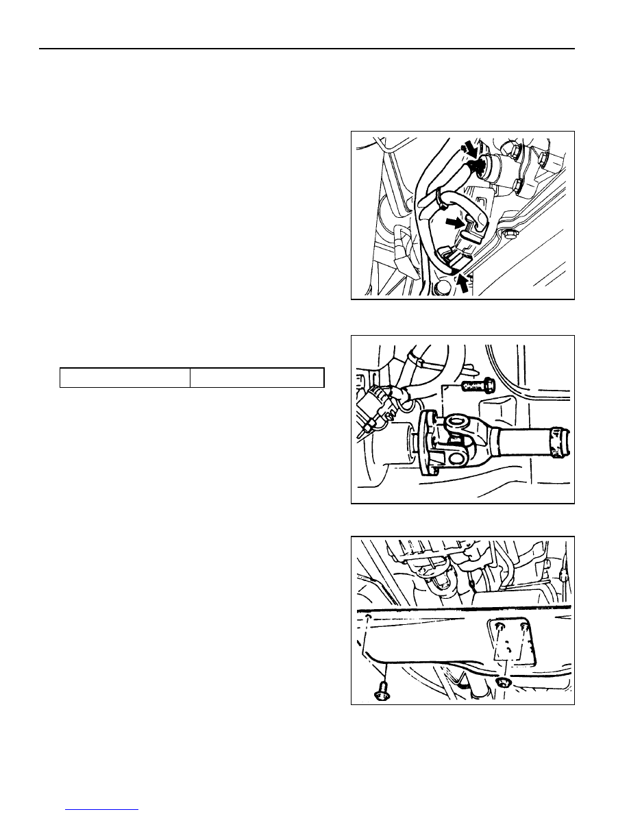
1. Disconnect the negative battery cable.
2. Disconnect the connectors from transfer case.
3. Disconnect the speedometer connector from transfer
case.
4. Disconnect the inhibitor and Sear position sensor
connector.
6. Unscrew the eight bolts and two nuts, and remove the
cross member.

AUTOMATIC TRANSMISSION 5A-83
Tightening Torque
70 - 80 Nm
11. Remove the two pipes for oil cooler.
Installation Notice
Tightening Torque
24.5 - 34.3 Nm
12. Remove the service hall cover on torque converter.
13. Put the alignment mark for installation, and unscrew the
six mounting bolts for torque converter from drive plate
through the service hole (arrow) by rotating the engine
and remove the torque converter.
Installation Notice
Tightening Torque
42 Nm
7. Remove the rear propeller shaft.
Installation Notice
8. Unscrew the five bolts and remove the transfer case.
9. Disconnect the 10-Pins Plug connector from transmission.
10. Separate the locking clip on shift lever and remove the
shift rod.
Notice
Removal and installation performed when the shift
procedure should be lever is in “D” range.
Screw the six bolts mounting the torque converter through
the service hole by using a mirror and rotating the engine.
Нет комментариевНе стесняйтесь поделиться с нами вашим ценным мнением.
Текст