Daewoo Musso. Manual — part 66
1B2-84 M161 ENGINE MECHANICAL
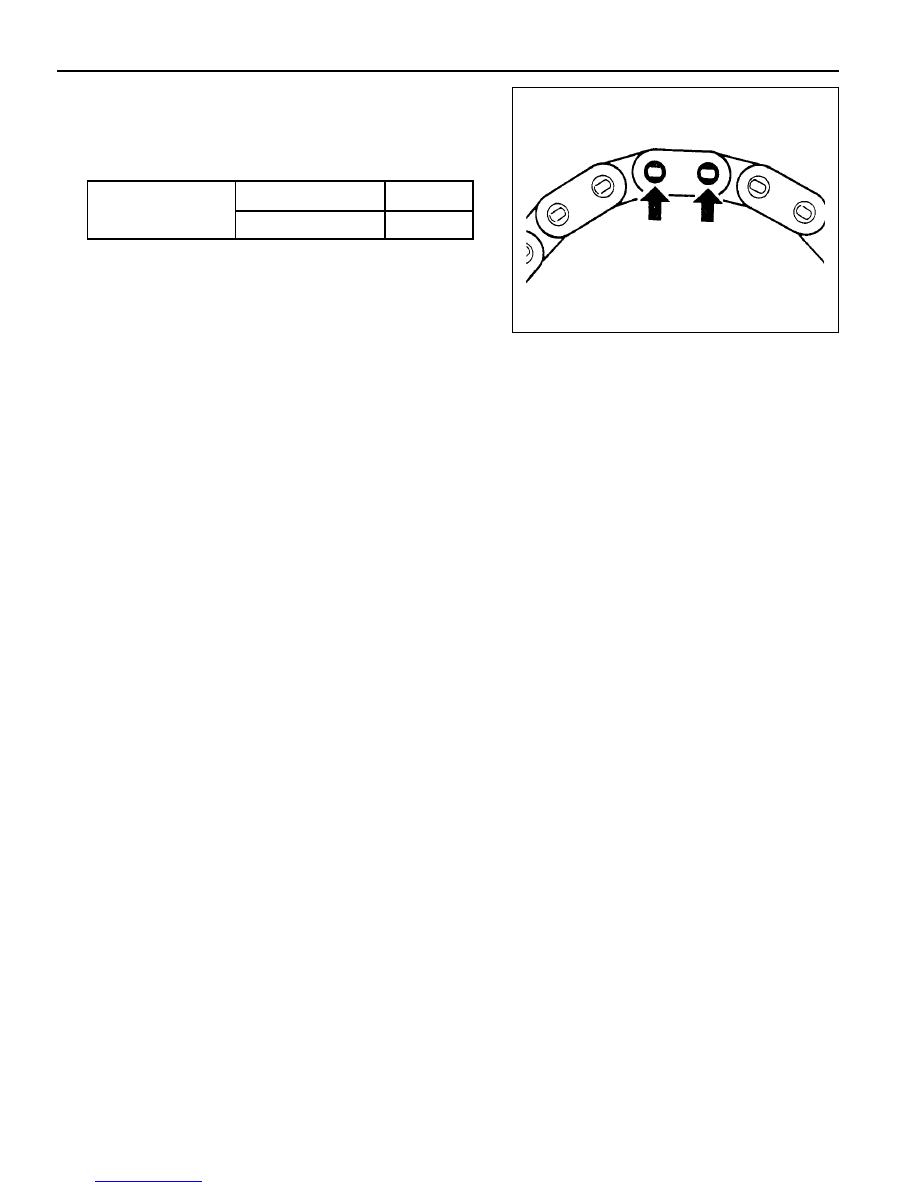
17. Rivet the link pin.
Check the condition and it again if necessary.
18. Install the chain tensioner.
Installation Notice
19. Check the camshaft timing position.
Tightening Torque
Screw Plug
40 Nm
Tensioner Assembly 72 - 88 Nm
M161 ENGINE MECHANICAL 1B2-85
TENSIONING RAIL
Preceding Work : Removal of cylinder head
Removal & Installation Procedure
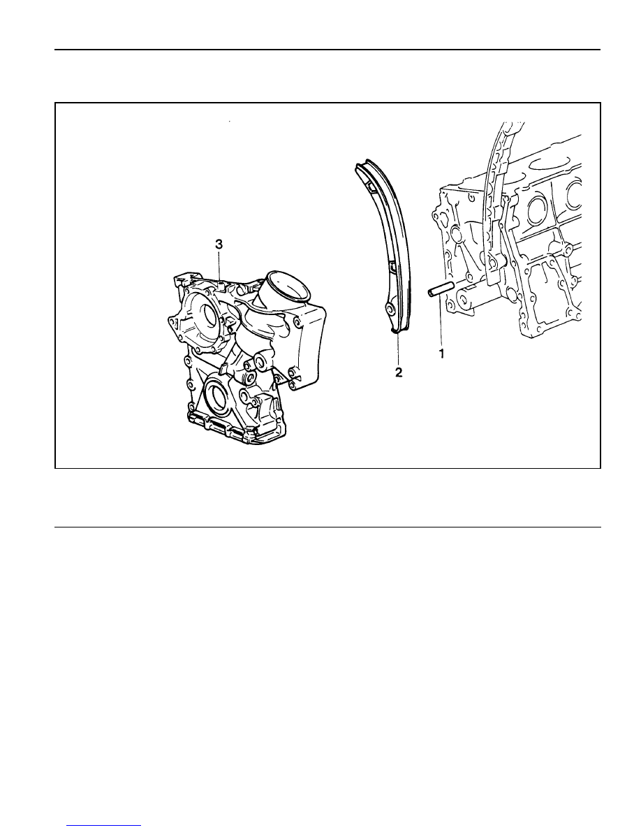
1. Remove the timing gear case cover (3).
Notice
Be careful not to damage the gasket.
2. Remove the sliding rail (1) from the sliding rail pin (2).
Notice
l
Replace the plastic guide (2) if it is damaged.
l
For installation, exactly align the plastic guide (2) with
the sliding rail (1).
3. Installation should follow the removal procedure in the
reverse order.
1 Sliding Rail Pin
2 Sliding Rail
3 Timing Gear Case Cover

1B2-86 M161 ENGINE MECHANICAL
CYLINDER HEAD GUIDE RAIL
Preceding Work : Removal of cylinder head cover
1 Bolt (M6 X 45, 2 pieces) . . . . .. 9-11 Nm
2 Guide Rail
Removal & Installation Procedure
1. Position the number 1 cylinder to ATDC20° guide rail.
2. Install the pin (special tool : 111 589 03 15 00) into the no.1
and no.6 bearing cap hole.
3. Remove the chain tensioner.
Installation Notice
Tightening Torque
Screw Plug
40 Nm
Tensioner Assembly
72 - 88 Nm
4. Unscrew the bolt (1) and remove the guide rail.
Installation Notice
Tightening Torque
9 - 11 Nm
5. Installation should follow the removal procedure in the
reverse order.

M161 ENGINE MECHANICAL 1B2-87
CRANKCASE GUIDE RAIL
Preceding Work : Removal of timing gear case cover
Removal & Installation Procedure
1. Remove the timing gear case cover (3).
Notice
Be careful not to damage the gasket when removing/
installing the timing gear case cover.
2. Remove the guide rail (2) from the guide rail pin(1).
Notice
l
Replace the plastic guide (2) if damaged.
l
Connect the plastic guide (2) and the guide rail (1) by
aligning them accurately when installing.
3. Installation should follow the removal procedure in the
reverse order.
1 Guide Rail Pin
2 Guide Rail
3 Timing Gear Case Cover
Нет комментариевНе стесняйтесь поделиться с нами вашим ценным мнением.
Текст