Daewoo Musso. Manual — part 269

5A-108 AUTOMATIC TRANSMISSION
12. Install the circlip.
13. Check the C3 clutch clearance (refer to figure 8.29) using
special tool No.0555-331900 in the following manner
(weight only).
a. Place the weight on the pressure plate and measure
the distance from the end of the cylinder to the top of
the pressure plate.
b. Record this figure.
c. Remove the weight.
d. Lift the pressure plate up against the circlip and
measure the distance from the end of
the cylinder to the top of the pressure plate.
e. Record this figure.
f.
Subtract the second reading from the first reading to
obtain the clutch pack clearance.
Notice
With the clutch pack supporting a weight of 2 kg, the
clearance between the snap ring and the top of the
pressure plate is to be between 1.20-1.45 mm.
14. If new friction plates are being fitted, remove the clutch
pack and soak the friction elements in automatic
transmission fluid for a minimum of five minutes prior to
reassembly.
Notice
The clutch pack clearance must be taken before the
elements are soaked in automatic transmission fluid.
Figure 8.29 - Typical C3 Clutch Assembly
Clearance

AUTOMATIC TRANSMISSION 5A-109
Forward Sun Gear and C3 Clutch Pack Assembly
To assemble the forward sun gear and C3 clutch pack assembly
(Refer to figure 8.30), proceed as follows:
1. Fit the No. 7 needle thrust bearing assembly over the forward
sun gear, ensuring that the thrust washer is between the
bearing and the sun gear.
2. Lubricate the thrust plate with petroleum jelly and fit the
thrust plate onto the reverse sun gear.
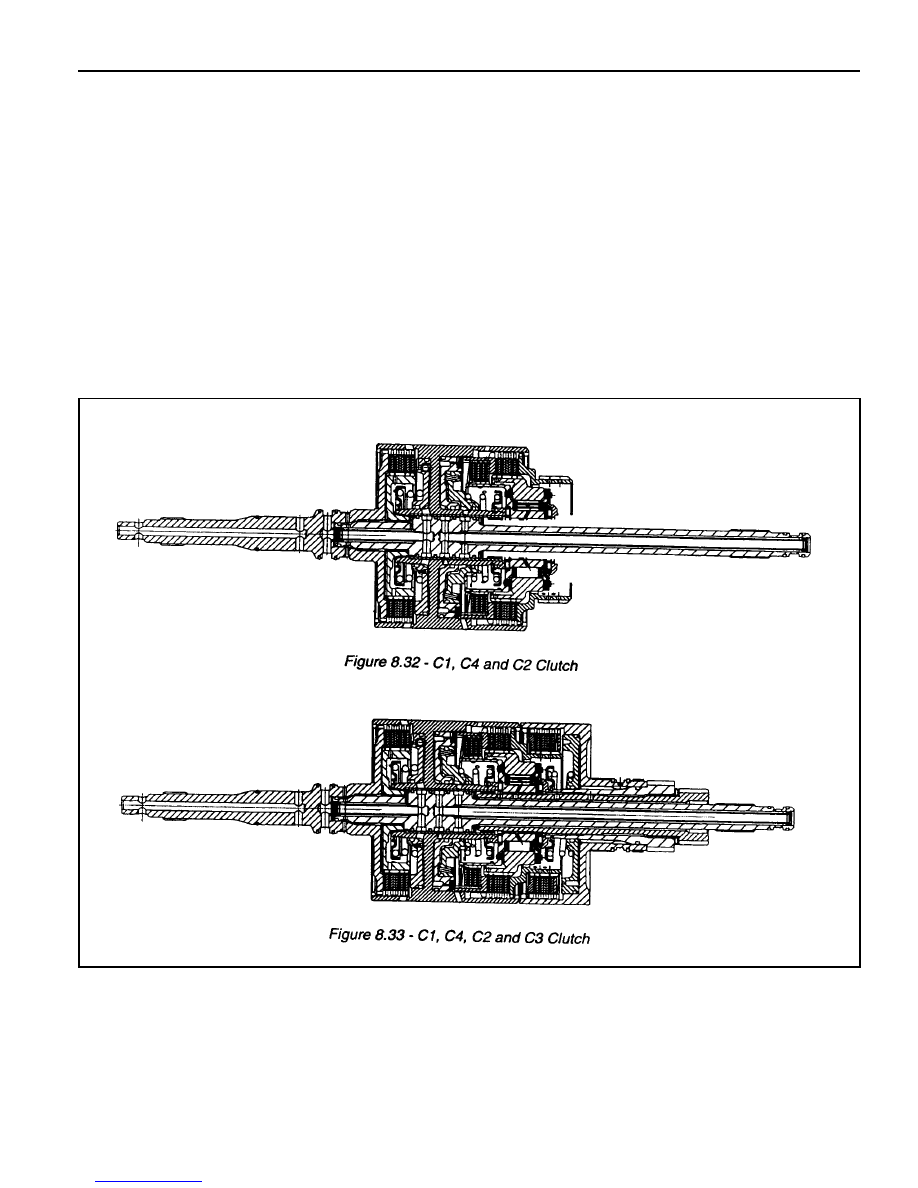
Refer to figure 8.33.
3. Align and fit the C3 clutch assembly over the forward sun
gear.
4. Lubricate the No. 6 needle thrust bearing with petroleum
jelly and fit it to the thrust plate. Ensure the lugs on the
outside diameter of the bearing fit in the thrust plate
counterbore.
Refer to figure 8.19.
5. Align and fit the plastic thrust washer to the thrust plate with
petroleum jelly.
Refer to to figures 8.19.
6. Install the assembly over the forward sun gear shaft against
the No.6 thrust bearing.
Refer to figure 8.19.
7. Place the assembly to one side.
Figure 8.30 - Typical forward Sun Gear add C3 Clutch Assembly

5A-110 AUTOMATIC TRANSMISSION
C1 Clutch Overdrive Shaft and Input Shaft
Assembly
Notice
1. Ensure that the snap rings are fitted correctly.
2. Check pistons for cracks, especially the C1 piston.
3. Do not mix clutch piston return springs.
4. If the C1/C2 clutch packs separate from the C3 clutch pack,
make sure the No. 6 bearing doesn’t drop out of the bearing
retainer.
To assemble the C1 clutch overdrive shaft and input shaft
assembly, proceed as follows:
1. Check the overdrive shaft grooves for any defect.
2. Coat the sealing rings, large and small, with petroleum jelly
and fit them to the overdrive shaft. The sealing rings may
be held in place with a small amount of petroleum jelly.
3. Assemble the clutch plate and disc into the cylinder in the
following sequence:
l
steel plate
l
friction disc
l
steel plate
l
friction disc
l
steel plate
l
steel plate - 0574-GOOGOl, 0574-000003,
0574-000004, 0574-000005, 0574-000020,
0574-000021, or friction disc -0574-000002
l
steel plate (selective)
l
friction disc
l
steel plate (selective)
l
friction disc
4. Check the clutch pack clearance using special tool No.0555-
331900. Refer to figure 8.31.
Use selective plates to achieve the correct specification.
Notice
The clutch pack supporting a 2 kg weight, the dimension
from the input shaft locating stop to the friction disc must
be 0.70-0.90 mm.
5. If new friction plates are being fitted, remove the clutch pack
and soak the friction elements in automatic transmission
fluid for a minimum of five minutes prior to assembly.
Notice
The clutch pack clearance must be taken before
elements are soaked in automatic transmission fluid.
6. Check the fit of the C1 clutch hub on the overdrive shaft. If
it is loose, the hub and shaft assembly must be replaced.
Figure 8.31 - Typical C1 Clutch Assembly
Clearance
AUTOMATIC TRANSMISSION 5A-111
7. Coat the small nylon thrust spacer with petroleum jelly and
install it over the overdrive shaft. Refer to figure 8.19.
8. Carefully fit the overdrive shaft into the C1 cylinder so as
not to damage the sealing ring.
9. Fit the small bronze C1 hub thrust washer in place with
petroleum jelly. Refer to figure 8.19.
10. Check the input shaft for any defect. Fit the input shaft
into the cylinder and secure it with the circlip, ensuring
that the circlip is completely seated in the groove.
11. Coat the sealing rings with petroleum jelly and fit onto the
input shaft.
12. Assemble the C1/C2/C4 clutch assembly to the C3 clutch
and sun gear assembly. Refer to figures 8.32 and 8.33.
13. Install this assembly in the transmission case.
Нет комментариевНе стесняйтесь поделиться с нами вашим ценным мнением.
Текст