Daewoo Musso. Manual — part 294
TRANSFER CASE (PART TIME 4408) 5D1-15
1 Nut
2 Spring Washer
3 Oil Seal
4 Companion Flange
5 Snap Ring
6 Torsional Damper
7 Pipe Plug
8 Bolt
9 Bolt
10 Speed Sensor and Harness
Bracket
11 Speed Sensor Assembly
12 Speed Sensor
13 O-Ring
14 Locking Clip
15 Connector
16 Motor Assembly
17 Oil Seal
18 Bearing
19 Bolt
20 Tag
21 Decal
22 Wiring Harness Clip
23 Bolt
24 Cover Assembly
25 Nut
26 Snap Ring
27 Bearing
28 Needle Bearing
29 Cover
30 Clutch Coil Assembly
31 Speed Gear
32 Oil Seal
33 Return Spring
34 Magnet
35 Clutch Housing
36 Lock-up Assembly
37 Snap Ring
38 Lock-up Hub
39 Sleeve Return Spring
40 Lock-up Collar
41 Rail Shaft
42 Lock-up Fork
43 Snap ring
44 Spacer
45 Driven Sprocket
46 Driven Sprocket
47 Drive Chain
48 Shaft and Pump Assembly
49 Screw
50 Pump Housing
51 Pump Gear Set
52 Pump Cover
53 Spring Pin
54 Hose Clamp
55 Hose Coupling
56 Oil Strainer
57 Output Shaft
58 Reduction Hub
59 Shift Fork Assembly
60 Shift Fork Facing
61 Pin, Roller and Retainer
62 Pin
63 Cam Roller
64 Retainer
65 Reduction Shift Fork
66 Nut
67 Plane Washer
68 Oil Seal
70 Companion Flange
71 Spacer
72 Front Output Assembly
73 Breather Hose
74 Bolt
75 Front Adapter Assembly
76 Snap Ring
77 Oil Seal
78 Spiral Pin
79 Front Adapter
80 Snap Ring
81 Bearing
82 Input Shaft Assembly
83 Sleeve Assembly
84 Needle Bearing
85 Input Shaft
86 Thrust Washer
87 Retaining Ring
88 Thrust Plate
89 Sun Gear
90 Gear Carrier Assembly
91 Planet Carrier
92 Pinion Shaft
93 Thrust Washer
94 Pinion Gear
95 Needle Roller Bearing
96 Pinion Needle Spacer
97 Electric Shift Cam
98 Torsion Spring
99 Spacer
100 Shift Shaft
101 Case Assembly
102 Oil Seal
103 Snap Ring
104 Bearing
105 Dowel Pin
106 Ring Gear
107 Case

5D1-16 TRANSFER CASE (PART TIME 4408)
Disassembly Procedure
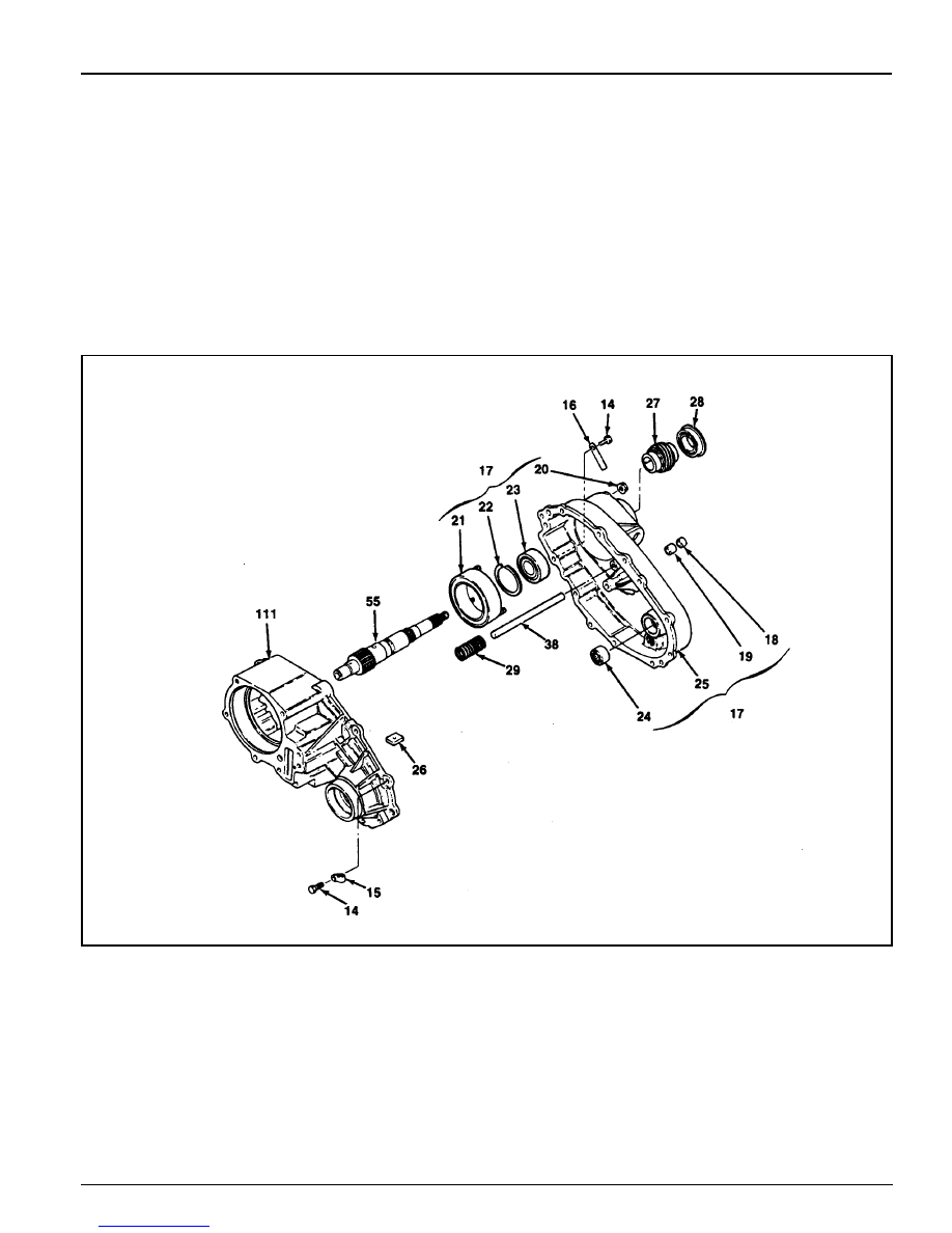
<Companion Flange>
1. Holding the companion flange, remove the nut and washer
and then remove the companion flange and oil seal.
2. Remove the 2 plugs from the cover.
1 Nut
2 Washer
3 Oil Seal
4 Companion Flange
5 Plug
25 Cover
6 Bolt
7 Washer
8 Bolt
9 Sensor and Harness Bracket
10 Sensor Assembly
11 Speed Sensor
12 O-ring
13 Motor Assembly
25 Cover
<Extension Electric Shift>
1. Remove the bolt, washer,3 bolts and harness bracket.
2. Remove the sensor assembly and remove the O-ring from
the speed sensor.
3. Remove the motor assembly.
TRANSFER CASE (PART TIME 4408) 5D1-17
1. Remove the 9 bolts, wiring harness clip and
identification tag.
Notice
Identification tag has information required for ordering
replacement parts, so be careful not to lose it.
2. Using a ‘-‘ driver, pry and disconnect the sealant
bond of the cover and required case.
3. Remove the oil seal, bearing, 3 nuts and clutch coil
assembly of the electric shift unit.
<Cover Assembly>
14 Bolt
15 Wiring Clip
16 Identification Tag
17 Cover Assembly
18 Oil Seal
19 Bearing
20 Nut
21 Clutch Coil Assembly
22 Snap Ring
23 Ball Bearing
4. Remove the snap ring and pull out the ball bearing
from the cover to remove the speed gear.
5. Pull out the needle bearing from the cover.
6. Pull out the oil seal from the slot in cover.
7. Remove the magnet form the slot in case.
8. Remove the return spring from the rail shaft.
9. Be careful not to damage the metal surface when
removing the sealant of the cover and case.
24 Needle Bearing
25 Cover
26 Magnet
27 Speed Gear
28 Oil Seal
29 Return Spring
38 Rail Shaft
55 Output Shaft
111 Transfer Case

5D1-18 TRANSFER CASE (PART TIME 4408)
<Lock-up Shift Parts>
1. Remove the retaining ring and clutch housing from the shift
collar hub.
2. Remove the shift collar hub from the output shaft.
3. Separate the 2WD - 4WD lock-up assembly and lock-up
fork from the output shaft and remove the rail shaft.
4. To remove the 2WD - 4WD lock-up assembly, separate the
return spring, lock-up hub and snap ring from the lock-up
collar.
30
Retaining Ring
31
Clutch Housing
32
Shift Collar Housing
33
2WD/4WD Lock-up Assembly
34
Snap Ring
35
Lock-up Hub
36
Return Spring
37
Lock-up Collar
38
Rail Shaft
39
Lock-up Fork
55
Output Shaft
40
Snap Ring
41
Spacer
42
Drive Sprocket
43
Driven Sprocket
44
Drive Chain
55
Output Shaft(Rear)
71
Output Shaft(Front)
<Drive Chains>
1. Remove the snap ring and spacer from the output shaft.
2. Remove the drive chain, driven sprocket and drive sprocket
from the output shaft.
3. Separate the chain and sprocket when removing the
assembly.
<Pump Parts>
1. Remove the 4 bolts and retainer and separate the output
shaft and rear pump cover.
2. Loosen the hose clamp and remove the hose coupling from
the pump housing.
3. Remove the hose clamp, hose coupling and strainer.
4. Remove 2 pump pins and spring from the output shaft.
5. Separate the front pump and remove the output shaft.
45
Shaft and Pump Assembly
46
Bolt
47
Pump Retainer
48
Rear Pump Cover
49
Hose Clamp
50
Hose Coupling
51
Pump Housing
52
Pump Pin
53
Spring
54
Front Pump Cover
55
Output Shaft
56
Strainer
Нет комментариевНе стесняйтесь поделиться с нами вашим ценным мнением.
Текст