Daewoo Musso. Manual — part 72

1B2-108 M161 ENGINE MECHANICAL
Group Code Letter and Cylinder Bore Size
CYLINDER BORE
Group Code Letter of Cylinder
A
X
B
X + 5
X + 10
A
X
B
X + 5
X + 10
Piston Type to be Used
A or X
A, X or B
X or B
X + 5
X + 10
A or X
A, X or B
X or B
X + 5
X + 10
Cylinder Bore Size (mm)
f
90.906 -
f
90.912
f
90.906 -
f
90.912
f
90.912 -
f
90.918
f
90.950 -
f
90.968
f
91.000 -
f
91.018
f
89.900 -
f
90.906
f
89.906 -
f
89.912
f
89.912 -
f
89.918
f
89.950 -
f
89.968
f
90.000 -
f
90.018
Engine
E23
E20

M161 ENGINE MECHANICAL 1B2-109
Service Data Standard
Measurement of Cylinder Bore
1. Clean the cylinder wall.
2. Using a internal diameter gauge, measure the bore size in
axial and transverse direction at three points (1,2,3).
1,2,3 Measuring Points
A. Axial Direction
B. Transverse Direction
a. Location of the No.1 Piston Ring at TDC
b. Location of the Piston BDC
c. Location of the Oil Ring at BDC
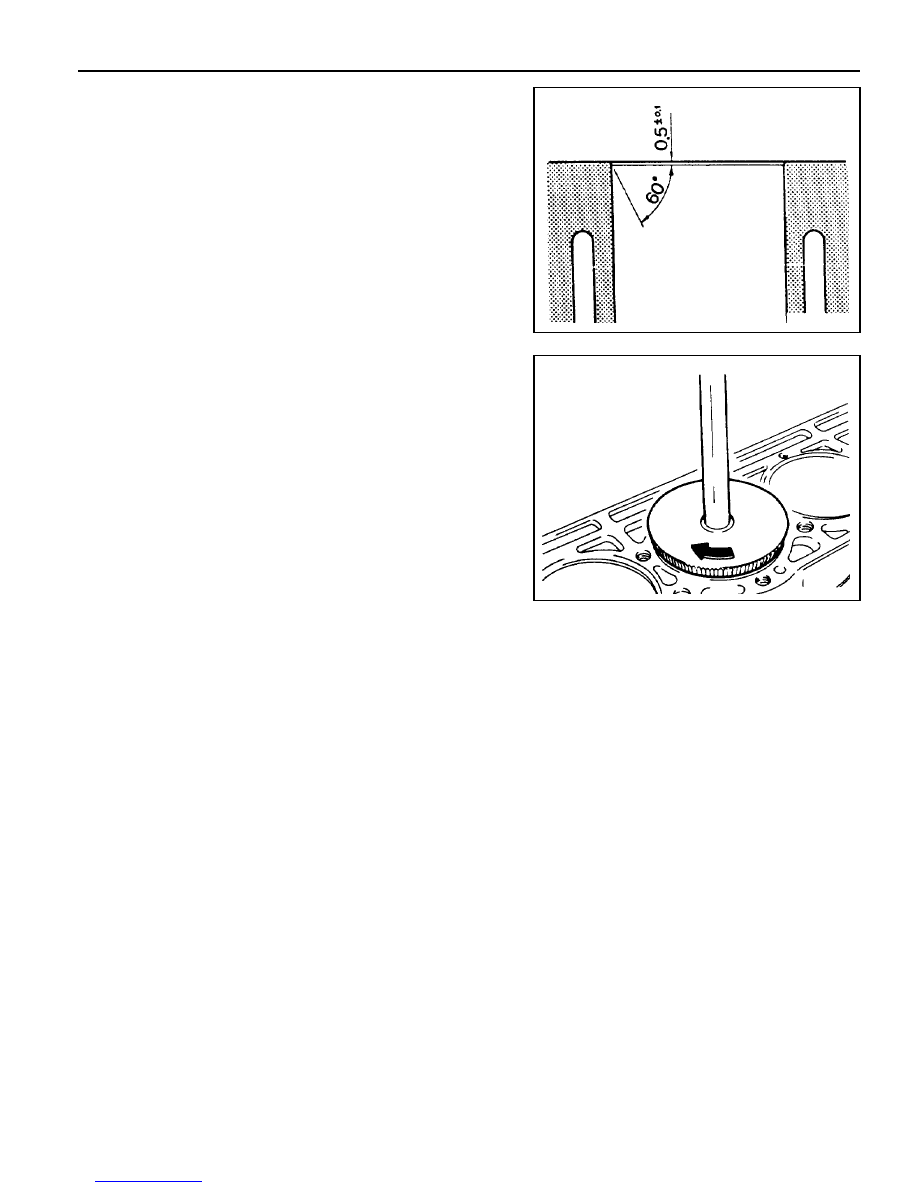
Chamfer Angle
Wear Limit in Longitudinal and Transverse Direction
Permissible Deviation of Cylinder Out-of-round
Permissible Deviation of Rectangular Cylinder Height (Except Chamfered Area)
Basic Peak-to-valley Height After Final Honing and Brushing
Chamfer Angle
Honing Angle
When new
Wear limit
0.1 mm
0.007 mm
0.05 mm
0.05 mm
0.003 - 0.006 mm
75°
50° ± 10°
1)
The group code letters are carved on the surface of the piston crown and in the mating surface of the crankcase.
Type
Standard Size
E20 :
f
89.9
E23 :
f
90.9
1st Repair Size
(Standard Size + 0.25)
2nd Repair Size
(Standard Size + 0.5)
Group Code Letter
1)
A
X
B
A
X
B
A
X
B
Cylinder Bore Size (mm)
f
89.900 -
f
90.906
f
89.906 -
f
89.912
f
89.912 -
f
89.918
f
90.150 -
f
90.156
f
89.156 -
f
90.162
f
90.162 -
f
90.168
f
90.400 -
f
90.406
f
90.406 -
f
90.412
f
90.412 -
f
90.418

1B2-110 M161 ENGINE MECHANICAL
CRANKCASE MATING SURFACE
Service Data Standard
Height of the Crankcase “H” (When New)
Minimum Height After Milling
Flatness
Permissible Deviation of Parallelism of the
Upper to Lower Mating Surface
Peak-to-valley Height
Crankcase Upper Mating Surface
Crankcase Lower Mating Surface
Axial Direction
Transverse Direction
Crankcase Upper Mating Surface
Crankcase Lower Mating Surface
289.35 - 289.45mm
289.05mm
0.03mm
0.04mm
0.1mm
0.05mm
0.012 - 0.009mm
0.025 - 0.020mm
M161 ENGINE MECHANICAL 1B2-111
Chamfering Procedure
1. Chamfer angle : 75°
2. Polish the lower chamfered area evenly with a grinder after
finishing the chamfering with a suitable tool (e.g., hand milling
cutter).
Нет комментариевНе стесняйтесь поделиться с нами вашим ценным мнением.
Текст