Daewoo Musso. Manual — part 61

1B2-64 M161 ENGINE MECHANICAL
7. Unscrew the bolt (3) from the armature (4) and remove
the roll pin, and remove the armature.
Installation Notice
Tightening Torque
35 Nm
8. Unscrew the nut (6) and remove the seal cover (7).
Installation Notice
Tightening Torque
60 - 70 Nm
Notice
Put the locking slot of nut toward armarture.
9. Take off the timing chain from intake camshaft sprocket.
10. Remove the cover (7), adjuster piston (9) and conical
spring (10) from intake camshaft sprocket.
11. Unscrew the bolt (11) and remove the flange shaft.
Installation Notice
Tightening Torque
1st step 20 Nm
2nd step + 95°
Notice
The flange bolt is designed to be used only once, so always
replace with new one.
12. Installation should follow the removal procedure in the
reverse order.
13. Check and adjust the camshaft timing.

M161 ENGINE MECHANICAL 1B2-65
CAMSHAFT SPROCKET BOLT
Intake Flange Shaft Bolt
Notice
The sprocket bolts are designed to be used only once, so
always replace with new one.
Exhaust Camshaft Sprocket Bolt
Notice
The sprocket bolts are designed to be used only once, so
always replace with new one.
C. M7 x 13 Collar Bolt Torx-T30
e. 6.8 mm
16. Flange Shaft
18. Control Piston
22. Intake Camshaft
E. M7 x 13 Collar Bolt Torx-T30
e. 6.8 mm
13a. Camshaft Sprocket
22a. Exhaust Camshaft
Tightening Torque
1st step 20 Nm
2nd step + 90°
Tightening Torque
1st step 20 Nm
2nd step + 90°
1B2-66 M161 ENGINE MECHANICAL
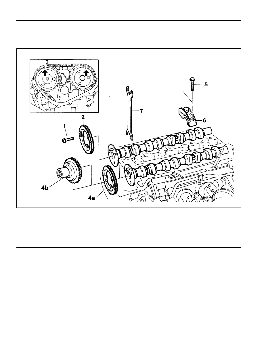
CAMSHAFT
Preceding Work : Removal of cylinder head cover
Removal of camshaft adjust actuator and cylinder head front cover
1 Bolt (M7 X 13, 3 pieces) . . . 1st Step 18-22 Nm
2nd Step 90°+ 5° Rotation Added
2 Exhaust Camshaft Sprocket
3 Timing Chain
4a Intake Camshaft Spocket (E20)
4b Camshaft Adjuster and Camshaft Sprocket (E23)
5 Bearing Cap Bolt (20 pieces) . . . 22.5-27.5 Nm
6 Camshaft Bearing Cap
7 Wrench (Special Tool)

M161 ENGINE MECHANICAL 1B2-67
Tools Required
000 589 01 10 00 Box Wrench Insert
104 589 01 01 00 Spanner
Removal & Installation Procedure
1. Turn the crankshaft and position the no.1 cylinder piston at
ATDC20°.
2. Put the alignment marks (arrows) on the camshaft sprocket
and the timing chain.
3. Remove the chain tensioner.
Installation Notice
Tightening Torque
40 Nm
72 - 88 Nm
Screw Plug
Tensioner Assembly
4. Remove the exhoust camshaft sprocket.
Installation Notice
Tightening Torque
1st step 35 - 45 Nm
2nd step 85° - 95°
Notice
The sprocket bolt is designed to be used only once, so
always replace with new one.
5. Take off the timing chain from intake camshaft sprocket,
and secute it not to fall down into the timing gear case.
6. Using the wrench (7), turn the camshaft until there is no
resistence in camshaft bearing area.
Нет комментариевНе стесняйтесь поделиться с нами вашим ценным мнением.
Текст