Daewoo Musso. Manual — part 122
1D1-8 M162 ENGINE COOLING
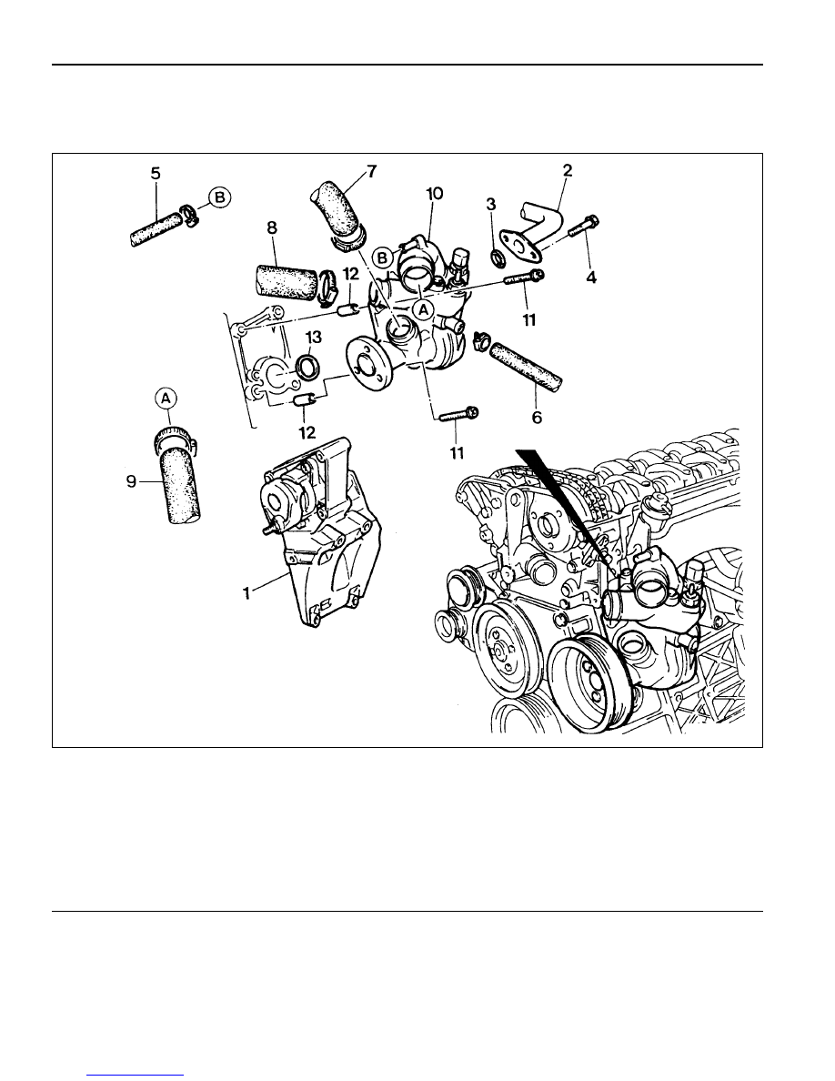
WATER PUMP
Preceding Work : Removal of V-belt
Removal of air admission housing
1 Air Admission Housing
2 Oil Cooler Pipe Line
3 Seal . . . . . . . . . . . . . ... Replace
4 Bolt . . . . . . . . . . . . . . 9-11 Nm
5 Coolant Hose
6 Coolant Hose
7 Outlet Coolant Hose
8 Coolant Hose
9 Inlet Coolant Hose
10 Coolant Pump
11 Bolt . . . . . . . . . . . . . . ... 21 Nm
12 Dowel Sleeve
13 Seal . . . . . . . . . . . . . ... Replace

M162 ENGINE COOLING 1D1-9
Removal & Installation Procedure
1. Drain the coolant.
2. Disconnect the coolant pump wire connector.
3. Loosen the hose clip and dsconnect all hoses from the
coolant pump
4. Remove the coolant line bolts (4) and then remove the
coolant line (2).
Installation Notice
Notice
Replace the seal (3).
5. Remove the mounting bolts (11) and carefully pull out
coolant pump (10).
Installation Notice
Tightening Torque
9 - 11 Nm
Notice
Replace the seal (13).
Tightening Torque
21 Nm
6. Installation should follow the removal procedure in the
reverse order.
7. Fill up coolant.
8. Do coolaing system leakage test

1D1-10 M162 ENGINE COOLING
THERMOSTAT
Removal & Installation Procedure
1. Drain the coolant from the radiator.
2. Loosen the hose mounting clamp (6) and remove the heater
hose (7).
3. Unscrew the three bolts (5) and remove the thermostat cover
bracket, thermostat cover and the thermostat in order.
Installation Notice
1 Thermostat Cover
2 Thermostat
3 O-ring
4 Thermostat Cover Bracket
5 Bolt (M6 X 25, 3 pieces) . . . . . . . 9-11 Nm
6 Hose Mounting Clamp
7 Heater Hose
Do not separate the thermostat cover and thermostat.
4. Replace the O-ring if necessary.
5. Check the leakage in the cooling system.
Tightening Torque
9 - 11 Nm
M162 ENGINE COOLING 1D1-11
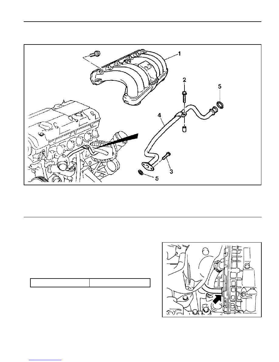
OIL COOLER PIPE LINE
Preceding Work : Removal of upper intake manifold
Tightening Torque
9 - 11 Nm
1 Upper Intake Manifold
2 Bolt (M6 X 35, 1 piece) . . . . . . ... 9-11 Nm
3 Bolt (M6 X 16, 2 pieces) . . . . . . . 9-11 Nm
4 Oil Cooler Pipe Line
5 O-ring . . . . . . . . . . . . . Replace
Removal & Installation Procedure
1. Drain the coolant.
2. Unscrew the bolts (2, 3) and remove the oil cooler pipe line (4).
Replace the O-ring with new one.
Installation Notice
3. Installation should follow the removal procedure in the
reverse order.
4. Fill up the coolant as specified.
5. Check the leaks in the cooling system.
Нет комментариевНе стесняйтесь поделиться с нами вашим ценным мнением.
Текст