Daewoo Musso. Manual — part 132

1D3-16 OM600 ENGINE COOLING
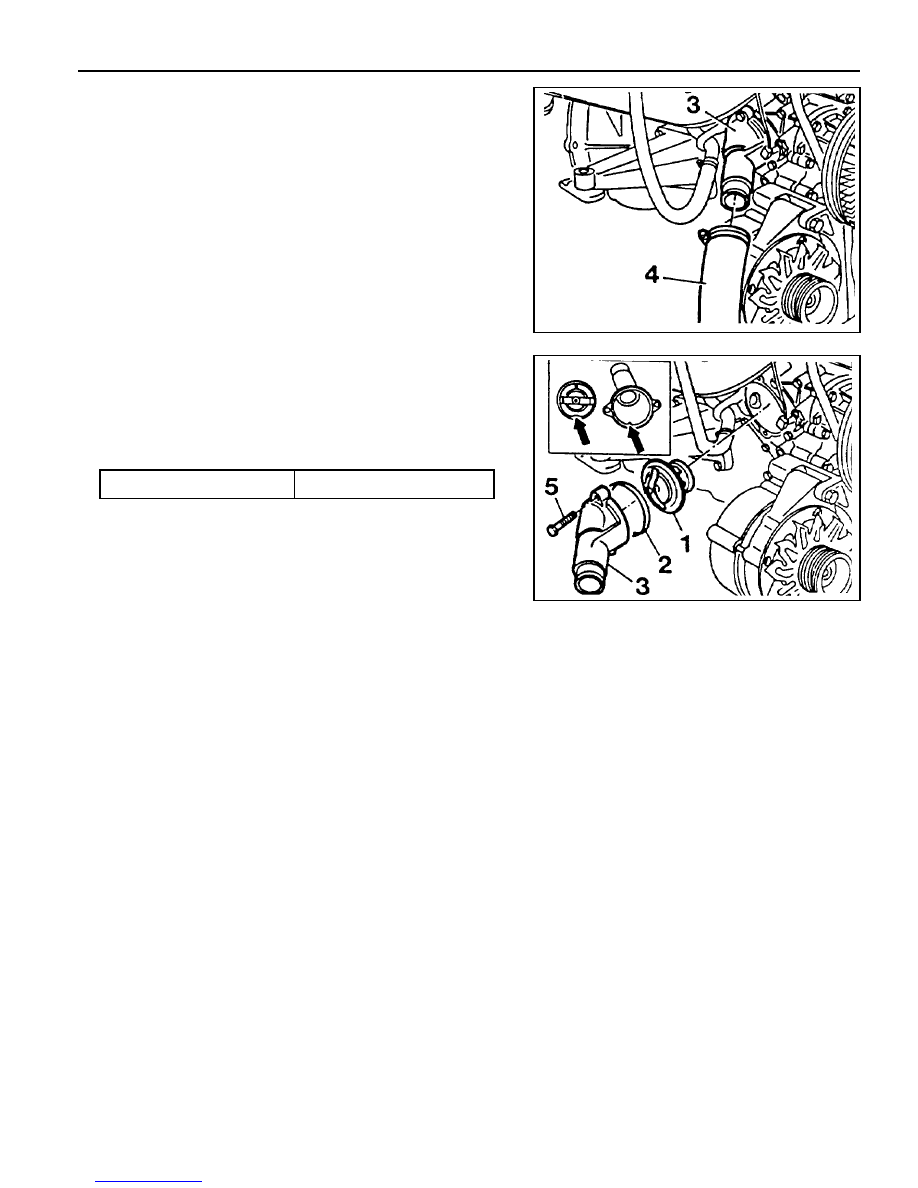
THERMOSTAT
1 Thermostat
2 Seal . . . . . . . . . . . . . ... Replace
3 Thermostat Housing Cover
4 Coolant Hose
5 Bolt . . . . . . . . . . . . . . . 10Nm
OM600 ENGINE COOLING 1D3-17
Removal & Installation Procedure
1. Drain the coolant completely.
2. Disconnect the coolant hose(4) from the thermostat housing
cover(3).
3. Remove the bolts(5) and then remove the thermostat(1)
and housing cover(3)
Installation Notice
Align the groove on thermostat and the housing cover
rib(arrow).
Tightening Torque
10 Nm
Notice
Replace the seal(2).
4. Installation should follow the removal procedure in the
reverse order.

SECTION 1E1
M162 ENGINE ELECTRICAL
Specifications . . . . . . . . . . . . . . . . . . . . . . . 1E1-1
Alternator Specifications . . . . . . . . . . . . . . . . 1E1-1
Starting Motor Specifications . . . . . . . . . . . . 1E1-2
Battery Specifications . . . . . . . . . . . . . . . . . . 1E1-2
Fastener Tightening Specifications . . . . . . . . 1E1-2
Special Tools . . . . . . . . . . . . . . . . . . . . . . . 1E1-3
Special Tools Table . . . . . . . . . . . . . . . . . . . . 1E1-3
Maintenance and Repair . . . . . . . . . . . . . . 1E1-4
On-Vehicle Service . . . . . . . . . . . . . . . . . . . . . 1E1-4
Alternator . . . . . . . . . . . . . . . . . . . . . . . . . . . 1E1-4
Starting Motor . . . . . . . . . . . . . . . . . . . . . . . . 1E1-5
Battery . . . . . . . . . . . . . . . . . . . . . . . . . . . . . 1E1-6
Spark Plug . . . . . . . . . . . . . . . . . . . . . . . . . . 1E1-7
Ignition Cable . . . . . . . . . . . . . . . . . . . . . . . . 1E1-9
Unit Repair . . . . . . . . . . . . . . . . . . . . . . . . 1E1-12
Battery . . . . . . . . . . . . . . . . . . . . . . . . . . . . 1E1-12
SPECIFICATIONS
ALTERNATOR SPECIFICATIONS
CAUTION: Disconnect the negative battery cable before removing or installing any electrical unit or when a
tool or equipment could easily come in contact with exposed electrical terminals. Disconnecting this cable
will help prevent personal injury and damage to the vehicle. The ignition must also be in LOCK unless otherwise
noted.
TABLE OF CONTENTS
Application
Output Voltage
Current
Resistance Between Rotor Core and Slip Ring
Description
12 - 14 V
115 A
¥ W

1E1-2 M162 ENGINE ELECTRICAL
N
·
m
14 - 18
4 - 5
45 - 50
12 - 15
6 - 7
35 - 48
12 - 18
12 - 18
12 - 18
9 - 11
9 - 11
25 - 30
STARTING MOTOR SPECIFICATIONS
Application
Voltage
Output Power
Description
12 V
1.7 KW
BATTERY SPECIFICATIONS
FASTENER TIGHTENING SPECIFICATIONS
Application
Capacity
Specific Gravity
Max. Tolerance Between Cells
Description
75 AH
³
1.24
³
0.04
Application
Alternator Terminal B+Nut
Alternator Terminal D+Nut
Alternator Combinction Bolt
Battery Cable Nut on Starting Motor
Electric Wire Nut on Starting Motor
Starting Motor Mounting Nut
Battery Mounting Bracket Nut
Battery Negative Cable
Battery Positive Cable
Ignition Cable Cover Bolt
Ignition Cable Bolt
Spark plug
Нет комментариевНе стесняйтесь поделиться с нами вашим ценным мнением.
Текст