Daewoo Musso. Manual — part 302
5D2-10 TRANSFER CASE (TOD)
Electric Shift System Operation
The Electric Shift System is responsible for changing the Transfer Case gear ratio by controlling the electric shift
motor. The TCCU monitors the 4H/4L switch, neutral switch, speed sensors, position encoder, and ignition switch.
A range change is initiated when
1. The 4H/4L Switch is changed from 4H to 4L or from 4L to 4H.
2. The motor position (as indicated by the position encoder) does not match the 4H/4L Switch immediately after the
ignition is turned on.
1. Shift Criteria
When a range change is initiated a Diagnostic Test will be completed on the motor, speed sensors, and position
encoder. If the Diagnostic Test fails, the shift will not be attempted. If all components are operating properly, the
TCCU will attempt a range change after the following shift criteria are met:
a. The transmission is in neutral for 2 seconds after the shift is requested.
b. Both propshaft speeds are below 87 rpm (2580 pulses/minute).
If the transmission is taken out of neutral before 2 seconds has elapsed, or either propshaft speed increases
above the limit, the shift will be suspended and the 4L Indicator will continue to blink until the criteria are met again
or the 4H/4L Switch is returned to the original position.
2. Range Change
When the shift criteria are met, the motor is rotated in the appropriate direction (as determined by the selector
switch) until one of the following occurs:
a. The motor reaches its destination.
b. The motor is on for 5 seconds without reaching its destination. The shift has failed and the TCCU will respond
as default mode.
c. A fault occurs with either the motor or position encoder. Refer to the diagnosis requirement.
When the motor is energized, the Ignition, 4H/4L Switch, propshaft speeds, and transmission neutral inputs are
ignored.
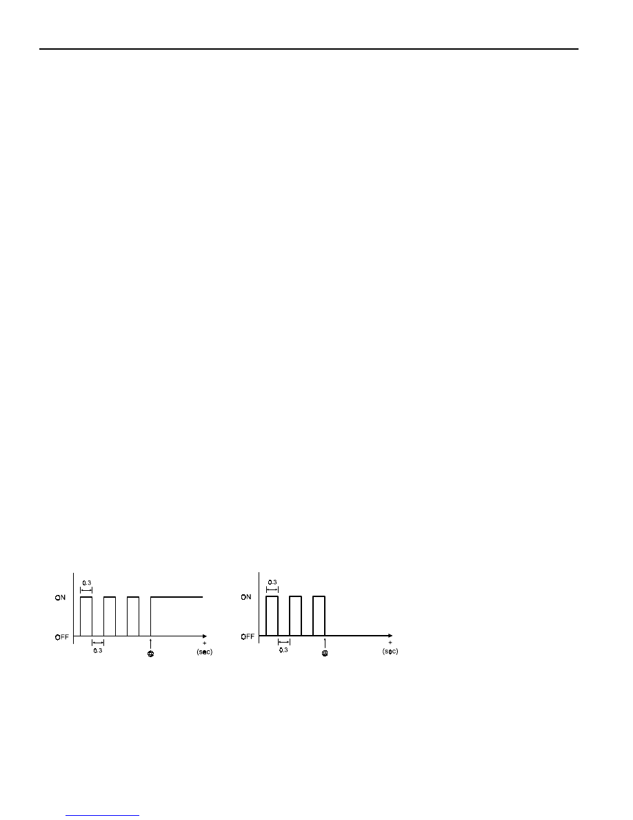
3. Indicator Function
Once a range change has been initiated the 4L Indicator will begin to blink at a rate of 0.3 seconds on, 0.3
seconds off until the shift is completed or canceled.
If a successful shift has been completed, the 4L Indicator will be illuminated if the motor is in Low and it will be
turned off if the motor is in High.
4L Indicator illuminates as below figure.
·
4H
®
4L
@ : shift is completed
·
4L
®
4H
@ : shift is completed
TRANSFER CASE (TOD) 5D2-11
4. Electric Shift Default Mode
If the motor fails to reach its destination, the TCCU will attempt the following (in order):
a. The TCCU will wait 3 seconds then attempt the shift again.
b. If the second attempt to reach the destination fails the TCCU will wait 3 seconds then attempt to rotate the
motor back to the original position. If successful, all future shifts will be inhibited until the Ignition is cycled.
c. If the attempt to return to the original position fails, the TCCU will wait 3 seconds then attempt to rotate the
motor to the original position again. If the second attempt to return to the original position is successful, the
“4WD CHECK” lamp will be illuminated, and all future shifts will be inhibited until the Ignition is cycled.
d. If the second attempt to return to the original position fails the motor will be turned off, the “4WD CHECK” lamp
will be illuminated, and all future shifts will be inhibited until the Ignition is cycled.
TOD
TM
System Operation
The TOD
TM
System is responsible for distributing torque between the front and rear axles. The TCCU monitors the
propshaft speeds, operating range (High/Low), and ABS activity and then applies a calculated amount of torque to
the front axle by Pulse Width Modulating the current applied to the EMC.
1. Touch-off Torque
The minimum EMC Duty Cycle is based on the vehicle speed and throttle position
The TCCU receives the TPS signal from the following sources:
On vehicles equipped with CAN, the TCCU receives the TPS signal from the CAN bus.
2. When Slip Detection
The TCCU continuously monitors the front and rear propshaft speeds to detect wheel slip.
3. Wheel Slip Control
When wheel slip is detected the TCCU controls the EMC duty cycle as necessary until the wheel slip is reduced
below the allowable limit. The EMC Duty Cycle will then be reduced to the Touch-Off value.
4. Brake/ABS Strategy
When the ABS System is active, the EMC Duty Cycle is set to a fixed duty cycle (30%) to aid in braking without
counteracting the ABS System.
5. 4L Strategy
When the system is operating in 4L, the TCCU continues TOD
TM
(operation provided that the propshaft speed is
below 175 rpm (5220 pulses/minute)). When the speed increases above 175 rpm, the EMC Duty Cycle is set to
the maximum value (88%) which applies the maximum available torque to the front axle.
5D2-12 TRANSFER CASE (TOD)
Pin
1
2
3
4
5
6
7
8
Function
Motor HI-LO
Motor LO-HI
EMC
Battery (+)
Ignition
Position Return
Diagnosis Display
-
Pin
9
10
11
12
13
14
15
16
Function
HI / LO Switch
Position 2
Front Speed
TPS Supply (Diesel)
Speed/TPS Return
Motor HI-LO
Motor LO-HI
Speed Reference
Pin
17
18
19
20
21
22
23
24
Function
Ground
Ground
Battery (+)
K-LINE
4L Illumination
CAN-H
CAN-L
Auto T/M, Neutral
Pin
25
26
27
28
29
30
-
-
Function
ABS Input
Brake Switch
Position 1
Position 3
Rear Speed
Position 4
-
-
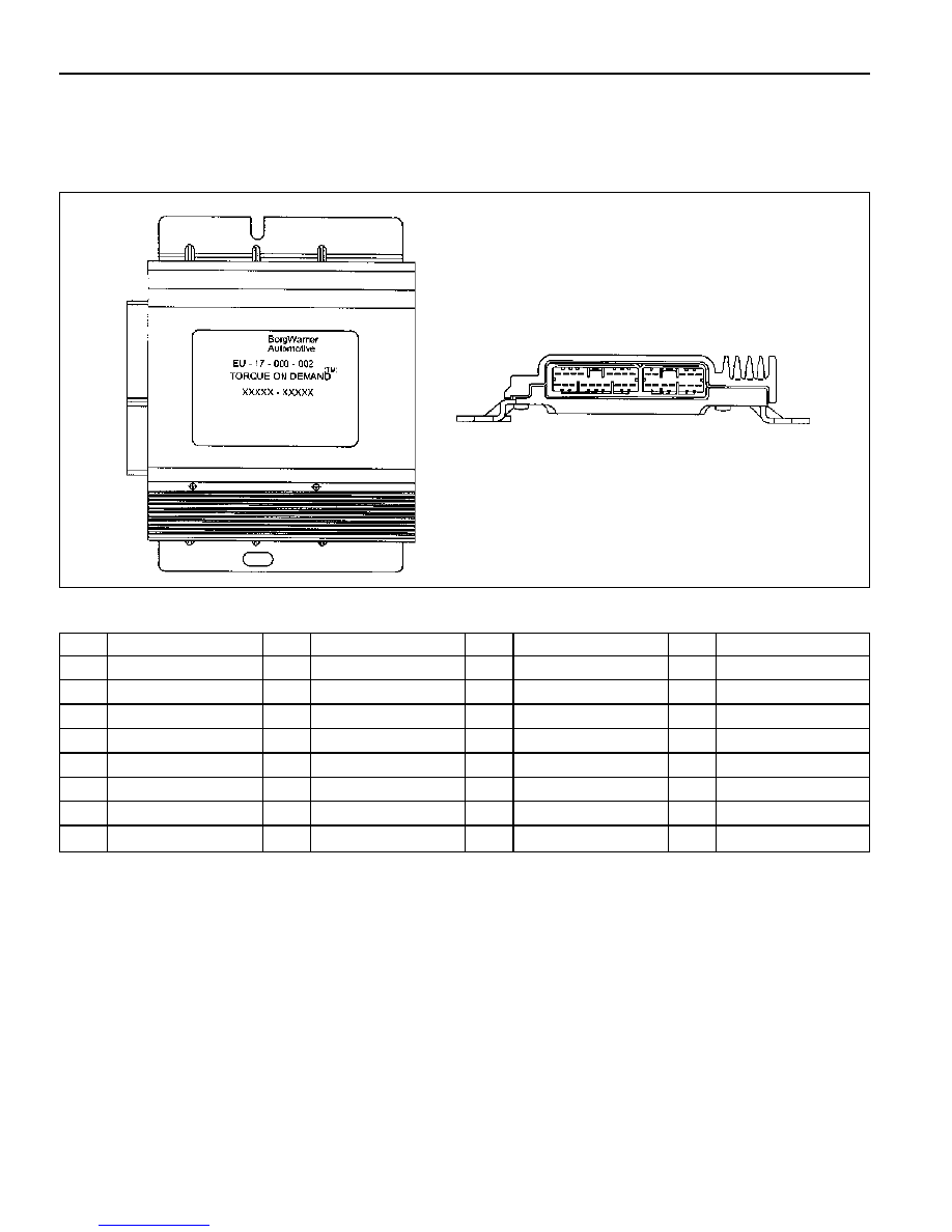
TOD CONTROL UNIT
Shape and function of TOD Control Unit

TRANSFER CASE (TOD) 5D2-13
Speed Sensor/Clutch Coil and Motor Connector
Speed senso /clutch coil and shift motor connector locate upper
backside transfer case (upper part of shift motor).
-
Shift motor connector : Black
-
Speed sensor and clutch coil connector : White
Shift Mtor Connector
Speed Sensor/Clutch Coil Connector
Rear View for Connector
Pin
A
B
C
D
E
F
G
Function
Position 4
Motor (Counter-Clockwise)
Position 3
Position 2
Position 1
Position Retum
Motor (Clockwise)
Pin
H
I
J
K
L
M
N
Function
Clutch Coil (EMC)
Front Speed Return
Front Speed
Front Speed Sensor Supply
Rear Speed Sensor Supply
Rear Speed
Rear Speed Return
Rear View for Connector
Нет комментариевНе стесняйтесь поделиться с нами вашим ценным мнением.
Текст