Dacia Solenza (engine E7J). Manual — part 15

ENGINE
E7J-262
10
ENGINE ASSEMBLY
10 - 35
DISTRIBUTION
Dismounting – Remounting
ENGINE E7J-262
10
ENGINE ASSEMBLY
10 - 36
DISTRIBUTION ADJUSTMENT
The belt tensioning is to be performed only
with cold engine (environment ambient tem-
perature).
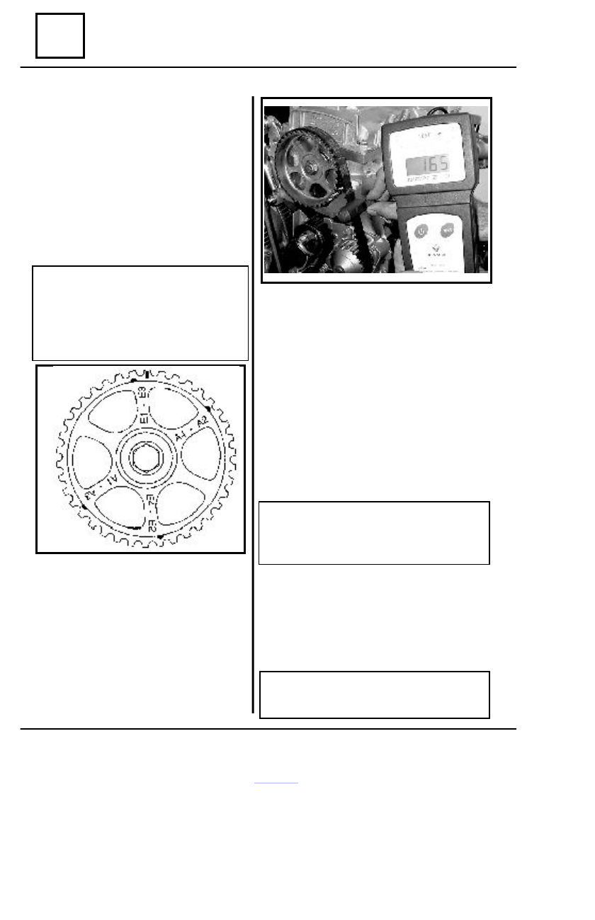
On the belt backside, there is an arrow
indicating the rotation direction and two marks
for setting.
Line up the L item from the crankshaft gear
with the M fix item (item from camshaft gear
upward).
ATTENTION!
The camshaft gear may have five
marks; only the rectangular shaped mark
of one tooth is representing UDP (Upper
Dead Point), the others are used for rock-
ers adjustment.
Dismounting – Remounting
Line up the items from the belt with the
ones from the gears, observing the mounting
direction and starting from the crankshaft
gear.
Place the MOT 1505 device captor (in
the position shown in the drawing) at a dis-
tance of 5-10 mm against the belt.
Any of the two captors may be used with
the condition that both captors are not in the
same time in front of the belt.
Make vibrating the belt by means of a finger
(the measurement is validated by a device “bip”)
Tighten the belt, by acting upon the tightening
roller by means of the MOT 1135-01 device,
until obtaining of a value between 210 and
275 Hz.
Block the tensioning roller and tighten its nut
to the required moment of 3 daNm.
Rotate then, five and a half turns the crankshaft
(cylinder no2 in the rockers adjustment position).
Dismount the tensioning roller nut.
Tighten again the distribution belt until
obtaining of a value between 145 and 185 Hz.
ATTENTION!
If the value of 275 Hz is exceeded, the
belt can not be used and its replacement is
necessary.
Obligatory tighten the rollers nut 0 to the re-
quired moment of 5 daNm.
If not, this may unloose risking the engine
damage.
REMARK:
Once a belt is dismounted, this is not to
be remounted, but replaced.
ENGINE
E7J-262
10
ENGINE ASSEMBLY
10 - 37
ROCKERS
ADJUSTMENT
Adjustment to be performed only with cold engine.
The adjustment values are:
- admission
0.10 mm
- exhaust
0.25 mm
1. Camshaft gear without marks.
a) Method called “ in balance”
Cylinders valves in balance
(exhaust end, admission beginning)
1
3
4
2
Adjust cylinder rocker
4
2
1
3
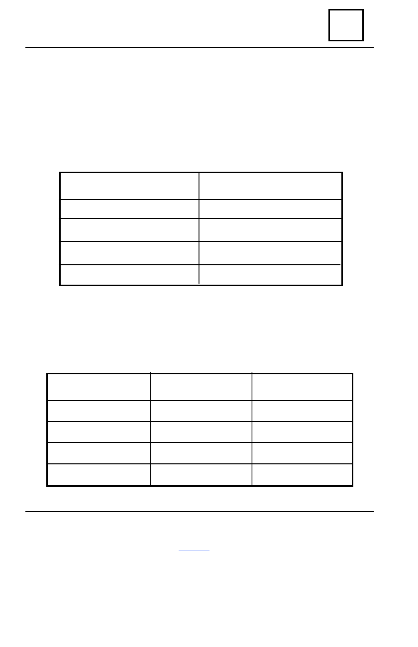
b) Method called “ exhaust valve maximum opened”
Rotate the engine (clockwise, as seen from distribution) until the exhaust valve of the cylinder
1 is reaching to the maximum opening and then adjust the clearance at the admission valve of the
cylinder 3 and the valve clearance of the cylinder 4.
Proceed in the same way also for the others cylinders as per next table:
Exhaust valve
Maximum opened
1
3
4
2
Admission valve to be
adjusted
3
4
2
1
Exhaust valve to be
adjusted
4
2
1
3
Dismounting – Remounting

ENGINE E7J-262
10
ENGINE ASSEMBLY
10 - 38
2. Camshaft gear with marks
Rotate the engine until is reaching the Upper
Dead Point (cylinder 1 at ignition), and then con-
tinue until first item:
- adjust : exhaust 1
exhaust 3
- at second item :
- adjust : admission 1
admission 3
- at third item :
- adjust : exhaust 2
exhaust 4
- at fourth item :
- adjust : admission 2
admission 4
Dismounting – Remounting
Continue to mount:
- cylinder head cover equipped with a new cylinder head gasket, tighten the attachment
screws to the required moment of 1 daNm;
- water inlet pipe and the oil dipper guide (with new sealing rings);
- distribution casings;
- crankshaft pulley or pulleys; tighten the pulley hub screw to the required moment of 2
daNm, then to 68° ± 6°.
ATTENTION!
If the screw is not properly tighten, this may unloose, which may lead to the oil pump
non-drive and to the distribution derangement, consequently to engine damaging.
- intake manifold and exhaust manifold, tighten the attachment screws to the required mo-
ment of 2.5 daNm;
- compressor and/or power steering support;
- alternator (see chapter 16”Alternator”);
- compressor- for vehicles equipped with air conditioning (see chapter 62 “Air condition-
ing”);
- power steering pump-for vehicles equipped with power steering (see chapter 36 “Power
steering pump”);
- belt or accessories belt according to the method described in chapter 07” Accessories
belt tensioning”.
Нет комментариевНе стесняйтесь поделиться с нами вашим ценным мнением.
Текст