Dacia Solenza (engine E7J). Manual — part 47
19
19 - 1
COOLING - EXHAUST - TANK
COOLING FLUID QUANTITY AND QUALITY
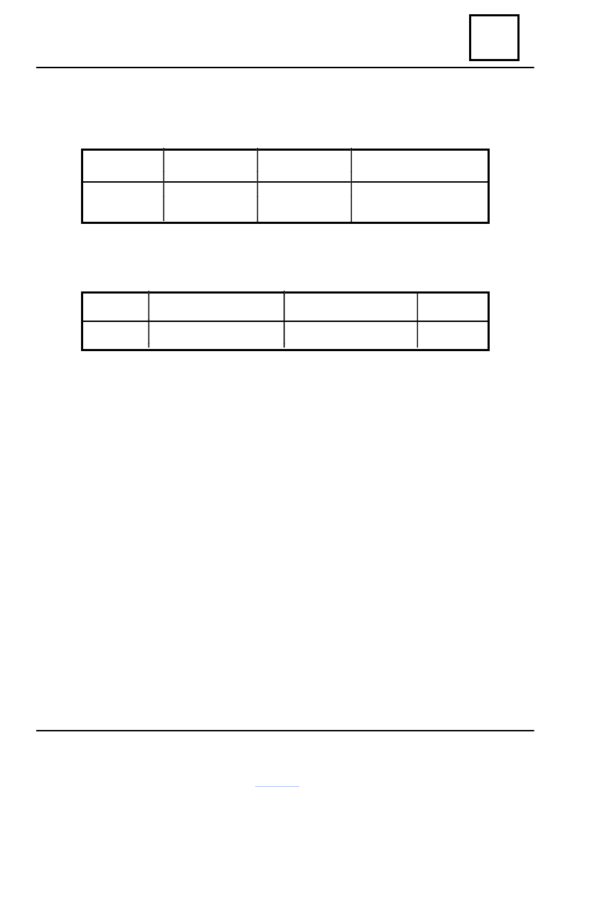
Characteristics
ENGINE
QUANTITY* (liters)
QUALITY
CHARACTERISTICS
E7J
6
Antifreeze type D
Protection until –40°C
GLACEOL RX
〈
Mixture : 50% concentrated antifreeze + 50% distilled water.
THERMOSTAT
ENGINE TYPE
OPENING START (°C)
OPENING
END (°C)
STROKE
(mm)
F8Q
89
101
7.5
19
19 - 2
COOLING - EXHAUST - TANK
The heating radiator has no valve.
The fluid circulation is permanently done in the heating radiator, this leading to the engine
cooling.
FILLING
Open the purging screw located on the water pipe between engine and climate control radiator.
Fill up the circuit by the expansion vessel hole
Tighten the purging screws in the moment when the fluid is flowing in a continuos jet.
Start the engine, maintaining it at 2500 rot/min.
Adjust the fluid level in the expansion vessel, during about 4 minutes.
Close the cap of the expansion vessel.
PURGING
Let the engine run for 10 minutes at 2500 rot/min, until engine fan starting (necessary
period for automatic gas purge).
Check if the fluid level in the expansion vessel is nearby the mark “Max”.
Do not open the purging screws with the engine running.
Retighten the expansion vessel cap with the warm engine.
Filling - Purging

19
19 - 3
COOLING - EXHAUST - TANK
Checking
SPECIAL TOOLS
MS 554-01
Adapter for M.S. 554-07
MS 554-06
Adapter for M.S. 554-07
MS 554-07
Kit for checking the cooling system sealing
1. CIRCUIT SEALING CHECKING
Mount the adapter M.S 554 –01 instead of
the expansion vessel valve.
Connect at the adapter, the M.S. 554-07
device.
Warm the engine, then stop it.
Pump, in order to create pressure in the cir-
cuit.
Stop pumping at a value lower with 0.1 bar
then the valve calibrating value (1.2 bar)
The pressure must not drop, if not, check for
leak and fix it.
Progressively
unscrew the device connection
for cooling circuit decompressing, then unscrew
the device, and mount back the expansion vessel
valve.
2. CHECKING ALVE CALIBRATION
Mount the expansion vessel valve on
adapter M.S. 554-06 and connect it to the
MS 557-07 device.
Pump to increase the pressure, this must
be stabilized at the valve calibration value 1.2
with a checking tolerance of ± 0.1 bar.
The calibration value of the expansion
vessel valve is: 1.2 bar.

19
19 - 4
COOLING - EXHAUST - TANK
Cooling system diagram
Thermostat
Water
pump
Composition :
1.
Engine
2.
Cooling radiator
3.
Expansion vessel
4.
Heating radiator
5.
Thermostat support
6.
Nozzle Ø 3
7.
Purging screw
T. Thermostat
The operation of the engine fan is controlled by the UCE injection, as follows:
1. For vehicles without air conditioning
–cooling engine fan cooling is starting when water temperature is over 99°C;
–cooling engine fan cooling is stopping when water temperature is lower than 96°C.
2. For the vehicles with air conditioning.
- cooling engine fan cooling is starting on first step when water temperature is over 99°C;
- cooling engine fan cooling is starting on second step when water temperature is over
104°C;
- cooling engine fan cooling is switching from second step to first step, when water
temperature is lower than 101°C;
- engine fan cooling is stopping when water temperature is lower than 96°C.
Нет комментариевНе стесняйтесь поделиться с нами вашим ценным мнением.
Текст