Dacia Solenza (engine E7J). Manual — part 21

ENGINE E7J - 262
14
14 - 1
ANTI-POLLUTION
Petrol vapors re-aspiration
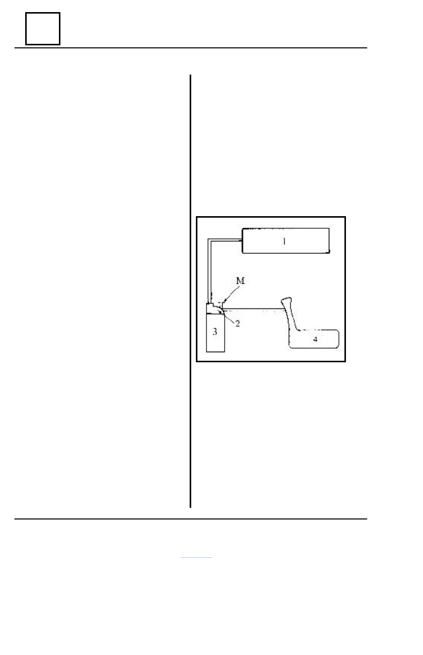
THE CIRCUIT OPERATING DIAGRAM
1 INTAKE MANIFOLD
2 CAN PURGING VALVE
3 CARBON CAN
4 FUEL TANK
M COMMUNICATION CONNECTION WITH ATMOSPHERE
ATTENTION !
For a normal operation of the circuit, the M connection must be clogged.
ENGINE E7J - 262
14
14 - 2
ANTI-POLLUTION
Petrol vapors re-aspiration
OPERATING PRINCIPLE
The communication of the tank with the
atmosphere is done through the carbon can.
The petrol vapors are retained when they are
passing through the active carbon from the carbon
can.
By means of a purging valve controlled by a
RCO signal issued by UCE injection, the petrol
vapors are re-aspired through piping by the intake
manifold.
The flow section of the purging valve is
variable, subject to the balance given by the
magnetic field created by supplying the purging
valve coil and the power of the spring ensuring
the valve closing.
RE-ASPIRATION CONDITIONS
The can-purging valve is controlled by pin
4 of the UCE injection, in the moment when:
- water temperature > 20 ° C;
- air temperature > 10 ° C;
- engine is running over a certain im-
posed charge;
- valve potentiometer is not in the posi-
tion acceleration pedal not pressed.
By using the CLIP tester, it is possible the
reading of the RCO value (opening cyclic
ratio).
The purging valve is closed for a value
smaller than 0.7%.
OPERATION CHECKING OF THE
CAN PURGING VALVE
A defective operation of the petrol vapors
re-aspiration system, may lead to an unstable
idling or even to the engine stopping.
First of all, check:
- circuit conformity (see the operating
diagram)
- piping condition between the can and
the fuel tank (sealing, circuit clogging).
The (B) piping coming from the tank shall
be clogged.
Connect a manometer (-3…+3 bar) at the
(M) connection for communication with the
atmosphere and check at idling if there is
depression.
Is there depression?
YES – Set contact off. Using a
vacuum pump, apply a 500 - mbar depression
at the (A) piping connection of the purging
valve. The value of the red depression must
not have a variation more than 10 mbar
within 10 seconds.

ENGINE E7J - 262
14
14 - 3
ANTI-POLLUTION
Petrol vapors re-aspiration
1
4
3
2
Petrol vapors re-aspiration
If the pressure is varying more than 10
mbar, then the purging valve is defective and
the carbon can assembly is to be replaced.
NO – When conditions for purging valve
controlling are accomplished and this one is
not opening, check its controlling electric
circuit (between UCE injection pin 4 and
purging valve), from point of view continuity
or short-circuit.
The RCO value of the signal received by
the purging value from the computer, may be
red by means of the CLIP tester in PR 023.
The minimal value is 0.7 % (corresponding
to the closing position of the purging valve).
LOCATION – DISMOUNTING
The carbon can assembly (1) with
incorporated purging valve, is placed on the
front right wing lining.
Disconnect the piping (2) coming from the
tank and piping (3) to the engine.
Disconnect the electric connector (4) of
the purging valve.
Remove the can from the attachment
support.
Perform the dismounting operations in
the reverse order
REMOUNTING
ENGINE E7J - 262
14
14 - 4
ANTI-POLLUTION
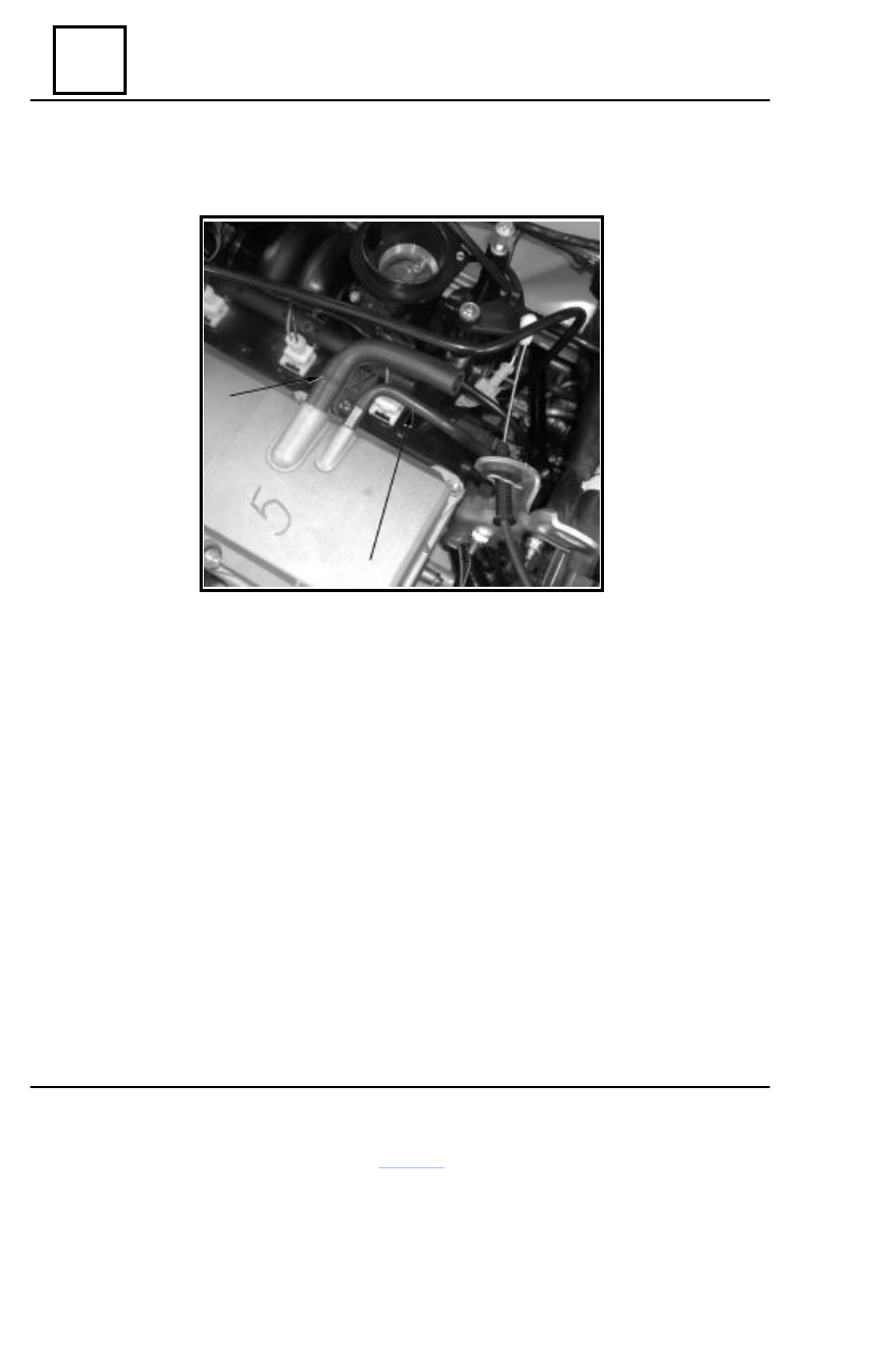
Oil vapors re-aspiration
1
2
CIRCUIT PRESENTATION
1 – Hose for oil vapors re-aspiration, connected upstream of valve body between cylinder
head cover and air filter case (the circuit is used for middle and big charges).
2 – Hose for oil vapors re-aspiration, connected downstream of valve body between cylinder
head cover and intake manifold.
For a correct operation of the oil vapors re-aspiration system, the hoses must be kept clean
and in good condition.
Нет комментариевНе стесняйтесь поделиться с нами вашим ценным мнением.
Текст