Dacia Solenza (engine E7J). Manual — part 112
INSIDE AND REAR LIGHTING
Inside and rear lighting
. . . . . . . . .
81-1
Ceiling lamp . . . . . . . . . . . . . ..
81-4
Bulbs . . . . . . . . . . . . . . . . ..
81-5
Lamps failures diagnostic . . . . . . . . .
81-6
Cockpit fuse box . . . . . . . . . . . ...
81-8
UCE decoder protection
. . . . . . . . .. 81-10
ACCOUSTIC WARNING - ANTI STARTING
General . . . . . . . . . . . . . . . ..
82-1
One key head replacement
. . . . . . . ...
82-5
Dismounting - remounting E.C.U. decoder
. .
82-6
Anti starting bushing replacement
. . . . ..
82-7
R.F. remote control for blocking/unlocking the
doors . . . . . . . . . . . . . . . . ... 82-8
Electric control unit injection replacement
. .
82-9
Acoustic warning . . . . . . . . . . . ... 82-10
Procedures . . . . . . . . . . . . . . . 82-12
Diagnostic . . . . . . . . . . . . . . .. 82-18
Diagnostic – General . . . . . . . . . . 82-39
Diagnostic – Failures interpretation
. . . ... 82-53
Diagnostic – Conformity checking . . . . ... 82-55
Diagnostic – States interpretation
. . . . ... 82-57
Diagnostic - Damage location algorithm
. . 82-63
INSTRUMENT PANEL
Instrument panel without RPM meter
. . . 83 -1
Instrument panel with RPM meter
. . . . .
83 -2
connectors disposal . . . . . . . . . . ... 83 -3
Perform functional instrument panel
. . . 83 -4
Speed transducer
. . . . . . . . . . . ..
83 -5
Fuel level transmitter . . . . . . . . . .
83 -6
Water temperature sensor
. . . . . . . .
83 -7
Diagnostic – damages interpretation
. . . .. 83 -8
STEERING - CONNECTOR
Anti-theft mechanism
. . . . . . . . . ..
84-1
Under steering wheel control
. . . . . . ..
84-2
Rear windows defrosting switch
. . . . . .
84-6
Central locking switch . . . . . . . . . ..
84-7
Passenger electric window switch
. . . . ...
84-8
Driver electric window switch
. . . . . . .
84-9
Hazard switch . . . . . . . . . . . . . 84-10
Electric lighter. . . . . . . . . . . . . . ..84-11
WINDSCREEN WIPER
Drive mechanism
. . . . . . . . . . . .
85-1
Diagnostic . . . . . . . . . . . . . . ...
85-3
AUTO RADIO
General . . . . . . . . . . . . . . . ..
86-1
Tapes player . . . . . . . . . . . . . ..
86-6
CD Player . . . . . . . . . . . . . . ..
86-7
Connectors . . . . . . . . . . . . . .
86-8
Roof antenna
. . . . . . . . . . . . .
86-9
ELECTRICAL ASSISANCE EQUIPEMENT
Windscreen washing . . . . . . . . . . .
87-1
Relays and UCE decoder assembly from
cockpit . . . . . . . . . . . . . . . ...
87-2
Cockpit Central Unit
. . . . . . . . . ...
87-4
Diagnostic – general . . . . . . . . . . .
87-6
Diagnostic – Failures interpretation
. . . . 87-11
Diagnostic - Conformity checking
. . . . ... 87-14
Diagnostic – States interpretation
. . . . ... 87-18
Diagnostic – Damage location algorithm
. . 87-26
WIRING
Airbag - general . . . . . . . . . . . .
88-1
Airbag – Electronic control unit
. . . . . .
88-2
Driver’s airbag . . . . . . . . . . . . ..
88-6
Airbag – Special devices . . . . . . . . ...
88-9
The airbag destroying procedure
. . . . . 88-10
Airbag diagnostic – General
. . . . . . . 88-12
Diagnostic – Failure interpretation
. . . . . 88-14
Diagnostic – Conformity checking
. . . . .. 88-20
Diagnostic – Help . . . . . . . . . . . .. 88-22
Diagnostic – Failure locating tree
. . . . . 88-23
Front door wiring protector
. . . . . . . 88-24
Rear door wiring protector
. . . . . . . .. 88-25
ELECTRIC DIAGRAMS
General . . . . . . . . . . . . . . . .. 89 - 1
Functional diagrams list
. . . . . . . . .. 89 - 6
Functional diagrams list index . . . . . . . 89 - 8
Connections lists - Mass list
. . . . . . . . 89 - 9
Electric components location on vehicle
. . . 89 - 10
Mass attachments on vehicle . . . . . . . 89 - 10
Electric components location on the vehicle . 89 - 11
Cockpit fuse box . . . . . . . . . . . . 89 - 14
Fuse box from engine compartment
. . . . 89 - 16
Wires functions index in connectors and
couplings . . . . . . . . . . . . . . ... 89 - 18
Wires functions in connectors and
couplings . . . . . . . . . . . . . . ... 89 - 21
Wires functions explanation
. . . . . . . 89 - 95
81
82
83
84
85
86
87
88
89
57
57 - 1
INSIDE ACCESSORIES
TIGHTENING MOMENTS(daNm)
Steering wheel attachment screw
4.4
Attachment screw steering wheel airbag
0.65
IMPORTANT !
All interventions at the airbag system
must be performed only by qualified
staff.
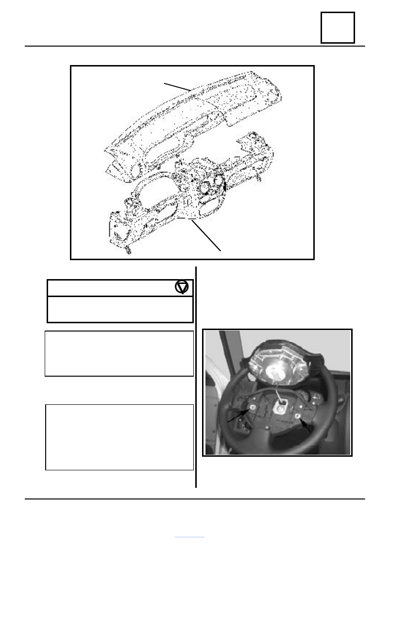
DISMOUNTING
IMPORTANT !
Before dismounting the airbag, block
the UCE airbag by means of the CLIP
tester (see chapter 88 “ UCE airbag
blocking”). The airbag indicator from
the instrument panel is on.
Disconnect the battery.
Dismount the two attachment screws of the
steering wheel airbag on the steering wheel by
means of a T20 (TORX) head screwdriver.
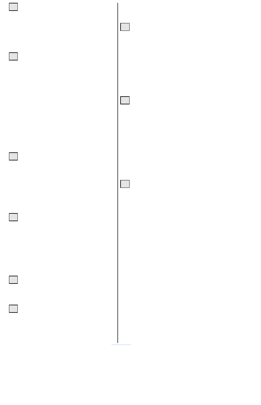
upper part dashboard
lower part dashboard
Disconnect the steering wheel airbag connec-
tor.
Dashboard
57
57 - 2
INSIDE ACCESSORIES
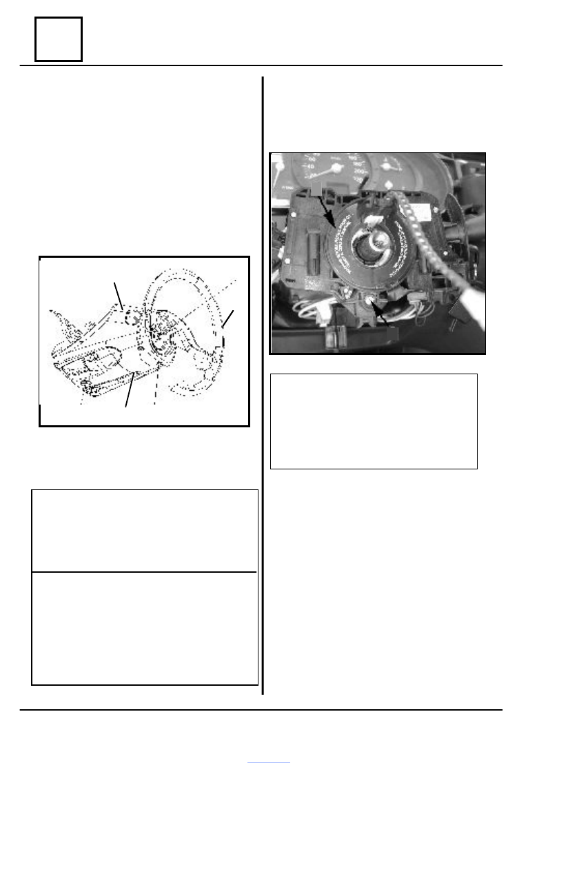
DISMOUNTING
Dismount :
- steering attachment screw (1) on the
steering column, by means of a screwdriver pro-
vided with TORX T50 head;
- steering wheel (2) not before bringing the
steering to the middle point (wheels are in a di-
rect line);
- half-cases (3) and (4) connected be-
tween them by three screws (5) to the steering
column.
In order to dismount the under steering wheel
control from the upper shaft of the steering
wheel, loosen the screw (6) and extract the
under steering wheel control (7).
5
1
2
4
3
5
Disconnect the connectors of :
- lights, windscreen wiper;
- anti-theft mechanism;
- rotating contact.
ATTENTION !
It is forbidden the handling of the pyro-
technic system near heating sources or open
fire, because there is the risk of undesirable
starting of the system.
IMPORTANT !
Anytime when dismounting the steering
wheel, it is necessary to dismount the airbag
connector (1). The airbag is provided with
a connector who is short-circuited after dis-
connecting the wiring connector, avoiding
in this way all undesirable starting.
ATTENTION !
It is forbidden the change of the rota-
tion contact position after dismounting
the under-steering wheel control assem-
bly, because there is the risk of its dam-
aging.
The under steering wheel control it is pro-
vided with a pre-cut self-adhesive tape
stacked on the rotating contact and on the
under steering wheel control body that is not
allowing the undesirable rotation of the rotat-
ing contact until its mounting on the attach-
ment cone of the steering column.
In case the position of the rotating contact
is changed, then this one, is to be rotated
clockwise 2.5 complete rotations (or until it
gets blocked), then is to be rotated anti-
clockwise 2.5 complete rotations.
7
6
Dashboard
57
57 - 3
INSIDE ACCESSORIES
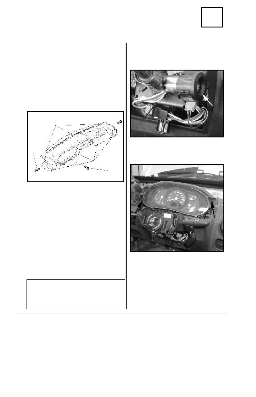
Dismount:
- two side attachment screws (8) of the
upper part dashboard by means of a wrench T
20(“L” shape);
- screws (9) attaching the upper part
dashboard with the lower part on the driving
post cross member, by means of a screwdriver
with T20 head.
Detach from clips placed in points (10) the
upper part dashboard.
Swing over the windscreen the upper part
dashboard and detach from clips points (11)
of the windscreen lower cross beam.
Detach from clips the radio from its sup-
port.
Disconnect the connectors and the radio
antenna (for the vehicle provided with radio-
cassettes player).
Disconnect the central locking connector
(for the vehicle provided with central locking).
Take out the upper part dashboard from the
cockpit.
REMARK :
Dismounting of the upper part dash-
board, does not imply steering wheel dis-
mounting.
Disconnect the anti-starting bushing connec-
tor.
Detach from clips the anti-starting bushing
(12).
8
8
10
9
11
12
13
13
Dismount the attachment screws (13) of the
instrument panel and disconnect the four con-
nectors.
Dashboard
Нет комментариевНе стесняйтесь поделиться с нами вашим ценным мнением.
Текст