Chery Tiggo 5 (T21). Service manual — part 55
06–
62
06
a. Use X-431 3G diagnostic tester to read the ECM DTC.
b. Refer to "DTC Confirmation Procedure".
c. Check if DTC P0116-00, P0117-00 or P0118-00 still exists.
7
Check for DTCs
Replace ECM
System is operating normally.
Reassemble vehicle and perform a road test to confirm that malfunction reported by customer has
been repaired.
NG
OK
06–
63
06
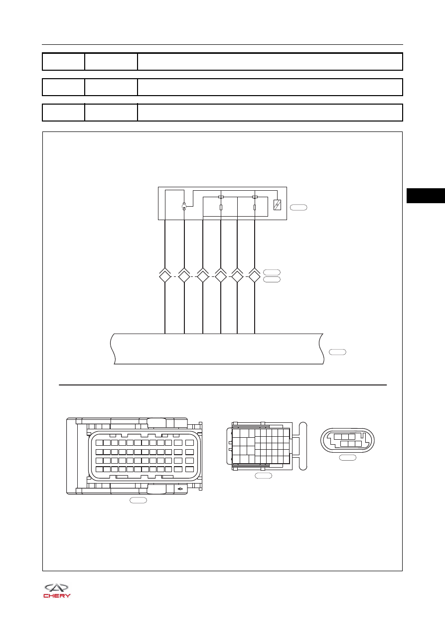
SQR484F ENGINE MANAGEMENT SYSTEM
DTC
P0121-00 Throttle/Pedal Pos. Sensor A Circ. Range/Performance
DTC
P0122-00 Throttle/Pedal Pos. Sensor A Circ. Low Input
DTC
P0123-00 Throttle/Pedal Pos. Sensor A Circ. High Input
ET21065006
37 38 39 40 41 42 43 44 45 46
47
48
25 26 27 28 29 30 31 32 33 34
35
36
13 14 15 16 17 18 19 20 21 22
23
24
1
2
3
4
5
6
7
8
9 10
11
12
B
E-035
1
4
2
5
3
6
1-23
1-11
1-22
1-14
1-43
1-13
RG
RL
RB
L
WL
RL
RG
RL
RB
R
WL
RL
ELECTRONIC
THROTTLE
M
8
5
7
4
6
3
1
2
3
4
5
6
7
8
9
10
11
12
13
14
15
16
17
18
19
20
21
22
23
24
25
26
31
35
39
40
41
42
32
33
36
37
38 34
27
28
29
30
B
E-007
E-007
E-038
1
2
3
4
5
6
B
E-009
E-009
ECM-1
E-035
06–
64
06
DTC Confirmation Procedure
Confirm that battery voltage is over 12 V before performing the following procedures.
Turn ignition switch to LOCK.
Connect X-431 3G diagnostic tester (the latest software) to Data Link Connector (DLC).
Turn ignition switch to ON.
Use X-431 3G diagnostic tester to record and clear the DTCs stored in the ECM.
Select Read Code.
If the DTC is detected, the malfunction indicated by the DTC is current. Go to the diagnosis
procedure - Step 1.
If DTC is not detected, the malfunction indicated by the DTC is intermittent (
).
Diagnosis Procedure
a. Turn ignition switch to LOCK.
b. Check ECM grounds E-026 and E-028 (
DTC Code
DTC Definitions
DTC Detection
Conditions
Possible Cause
P0121-00
Throttle/Pedal Pos.
Sensor A Circ. Range/
Performance
Ignition switch ON
Engine running
Throttle position sensor 1
Wire harness or connector
ECM
P0122-00
Throttle/Pedal Pos.
Sensor A Circ. Low
Input
P0123-00
Throttle/Pedal Pos.
Sensor A Circ. High
Input
CAUTION
When performing circuit diagnosis and test, always refer to the circuit diagram for specific circuit and
component information.
1
Check ECM ground point
Repair or replace ground wire harness or
ground point
NG
OK
06–
65
06
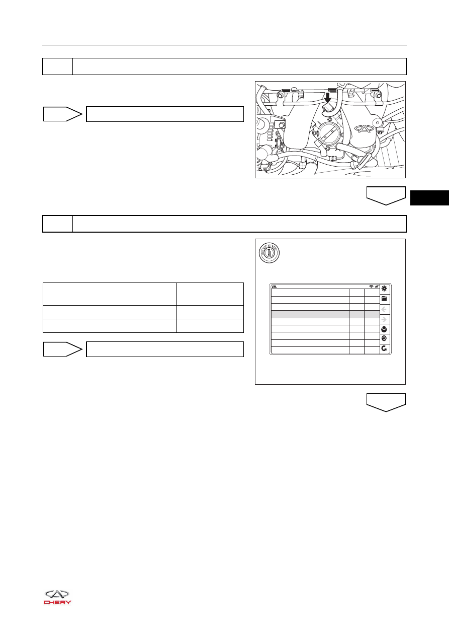
a. Disconnect electronic throttle connector E-009.
b. Check electronic throttle connector.
a. Connect throttle position sensor connector E-009.
b. Turn ignition switch to ON.
c. Using diagnostic tester, check throttle position sensor 1
signal voltage.
2
Check electronic throttle connector
RT21060110
Repair or replace connector
NG
3
Check throttle position sensor 1 signal voltage
OK
RT21060120
sensor voltage from throttle potentiometer 1
sensor voltage from throttle potentiometer 2
additive correction of the mixture adaptation
Voltage PWG potentiometer 1
Voltage PWG potentiometer 2
Doubled PWG potentiometer-2 voltage
multiplicative correction of the mixture adaptation
lambda controller output
Datastream name
Value
1.00
1.03
0.00
0.77
0.38
0.75
0.78
V
V
V
V
V
%
4.22
Unit
Datastream
Condition
Standard Value
(V)
Accelerator pedal released
0.78
Accelerator pedal depressed
4.29
Go to step 8
OK
NG
Нет комментариевНе стесняйтесь поделиться с нами вашим ценным мнением.
Текст