Chery Tiggo 5 (T21). Service manual — part 435
38–
21
38
DTC
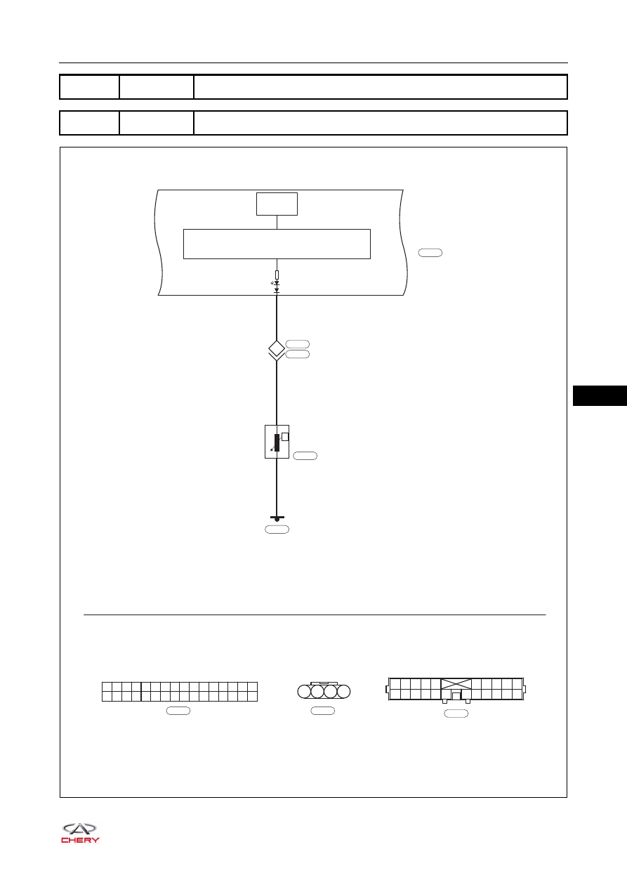
B1101-11 Fuel Sensor Fault Circuit Short to Ground
DTC
B1101-15 Fuel Sensor Fault Circuit Short to Battery or Open
32
31
30
29
28
16
15
14
13
12
11
10
9
8
7
6
5
4
3
2
1
27
26
25
24
23
22
21
20
19
18
17
Br
B-032
21
VB
VB
12
1
2
Q
FUEL
PUMP
MOTOR
INSTRUMENT
CLUSTER
I-015
L
I-015
1
2
3
4
5
6
7
8
9
10
11
12
13
14
15
16
17
18
19
20
21
22
W
I-006
I-006
B-003
B-038
MICROPROCESSOR
FUEL
GAUGE
lOW FUEL
LEVEL
1
2
3
4
B
B-038
ET21380060
38–
22
38
Self-diagnosis Detection Logic
Diagnosis Procedure
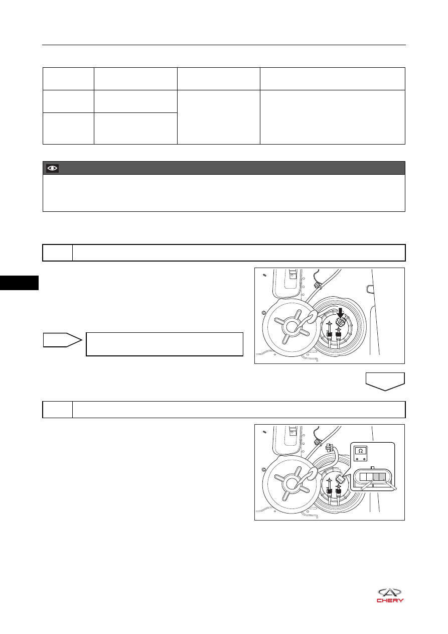
a. Turn ignition switch to LOCK.
b. Disconnect the negative battery cable.
c. Disconnect the fuel level sensor and fuel pump connector
B-038.
d. Check the wire harness, connector and terminals for
deformation, bend or damage.
a. Connect the negative battery cable.
b. Turn ignition switch to ON.
c. Check the remaining oil amount segments from fuel
gauge in the instrument cluster.
d. Turn ignition switch to LOCK.
e. Disconnect the negative battery cable.
f. Disconnect the fuel level sensor and fuel pump connector
B-038.
g. Using a digital multimeter, measure the resistance
between terminal 1 and terminal 2 of fuel level sensor.
h. Check if fuel level sensor is normal according to the
correspondence between fuel amount segments and
standard resistance of fuel level sensor as shown in the
table below.
DTC Code
DTC Definition
DTC Detection
Condition
Possible Cause
B1101-11
Fuel Sensor Fault
Circuit Short to Ground
Ignition switch ON
Charging system
Wire harness or connector
Instrument cluster
B1101-15
Fuel Sensor Fault
Circuit Short to Battery
or Open
CAUTION
When performing circuit diagnosis and test, always refer to circuit diagram for specific circuit and
component information.
1
Check fuel level sensor wire harness and connector
RT21380060
Repair or replace fuel level sensor wire
harness and connector
NG
2
Check fuel level sensor
OK
RT21380050
-
+
1
2
3
4
38–
23
38
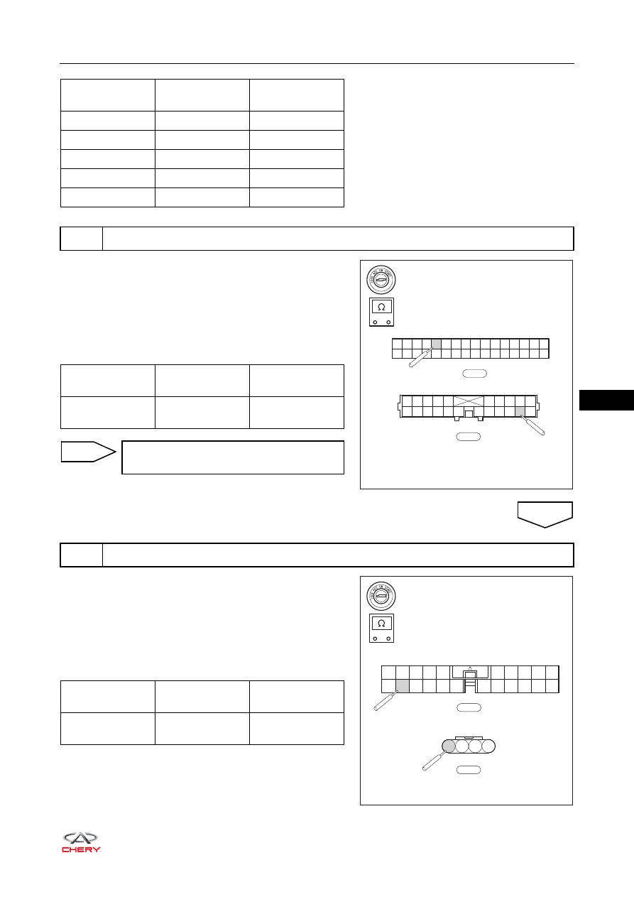
a. Turn ignition switch to LOCK.
b. Disconnect the negative battery cable.
c. Disconnect the instrument panel wire harness connectors
I-015 and I-006.
d. Using a digital multimeter, check for continuity between
instrument panel wire harness connectors I-015 and
I-006 according to the table below.
a. Turn ignition switch to LOCK.
b. Disconnect the negative battery cable.
c. Disconnect the body wire harness connectors B-003 and
B-038.
d. Using a digital multimeter, check for continuity between
body wire harness connectors B-003 and B-038
according to the table below.
Fuel Gauge
Position
Multimeter
Connection
Specification (Ω)
E
1 - 2
275 ± 5
1/4
1 - 2
165 ± 5
1/2
1 - 2
97 ± 4
3/4
1 - 2
79 ± 3
F
1 - 2
32 ± 3
3
Check instrument panel wire harness and connector
RT21380130
32
31
30
29
28
16
15
14
13
12
11
10
9
8
7
6
5
4
3
2
1
27
26
25
24
23
22
21
20
19
18
17
I-015
-
+
1
2
3
4
5
6
7
8
9
10
11
12
13
14
15
16
17
18
19
20
21
22
I-006
Multimeter
Connection
Condition
Specified
Condition
I-015 (21) -
I-006 (12)
Always
Continuity
Repair or replace instrument panel wire
harness and connector
NG
4
Check body wire harness and connector
OK
RT21380140
-
+
1
2
3
4
5
11
12
13
14
15
16
17 18
19
20
21
22
6
7
8
9
10
B-003
1
2
3
4
B-038
Multimeter
Connection
Condition
Specified
Condition
B-003 (12) -
B-038 (1)
Always
Continuity
38–
24
38
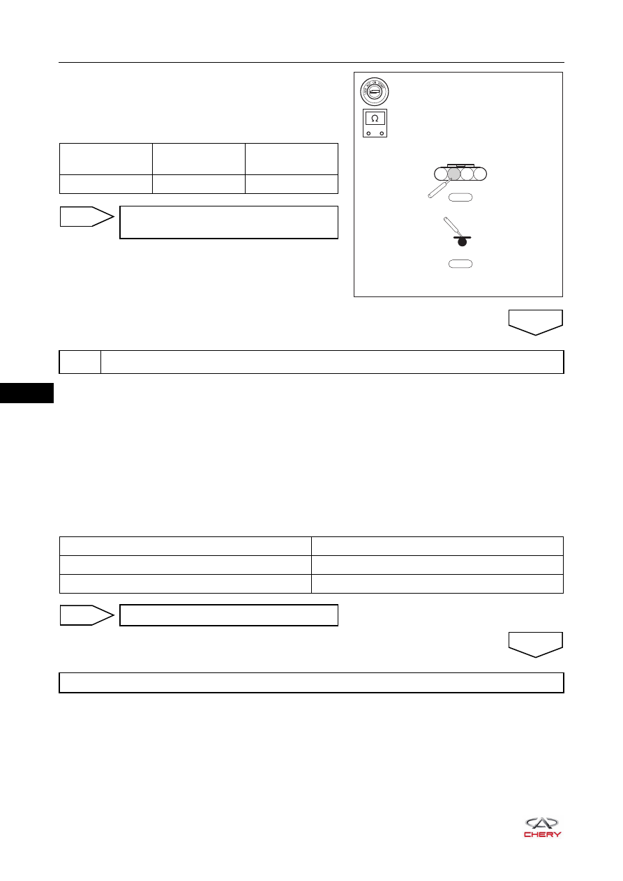
e. Disconnect the body wire harness connector B-038 and
ground B-032.
f. Using a digital multimeter, check for continuity between
body wire harness connector B-038 and ground B-032
according to the table below.
a. Connect all connectors.
b. Connect the negative battery cable.
c. Turn ignition switch to ON.
d. Use X-431 3G diagnostic tester (the latest software) to record and clear the DTCs stored in the instrument
panel control system.
e. Turn ignition switch to LOCK and wait for a few seconds.
f. Turn ignition switch to ON.
g. Use X-431 3G diagnostic tester (the latest software) to read the DTCs in the instrument cluster system
again.
h. Read the DTCs.
RT21380150
-
+
1
2
3
4
B-038
B-032
Multimeter
Connection
Condition
Specified
Condition
B-038 (2) - B-032
Always
Continuity
Repair or replace body wire harness and
connector
NG
5
Reconfirm DTCs
OK
Result
Proceed to
DTC B1101-11 and B1101-15 are output
NG
No DTC is output
OK
Replace instrument cluster
System is normal
NG
OK
Нет комментариевНе стесняйтесь поделиться с нами вашим ценным мнением.
Текст