Chery Tiggo 5 (T21). Service manual — part 283
25–
65
25
a. Turn ignition switch to LOCK.
b. Disconnect the negative battery cable.
c. Disconnect the ABS control module assembly connector
E-085.
d. Using a digital multimeter, check for continuity between
ABS control module assembly connector E-085 and body
ground to check if the system ground circuit is normal
according to the table below.
Standard Condition
a. Use X-431 3G diagnostic tester to clear the DTC.
b. Start the engine.
c. Drive the vehicle at 15 km/h or more, read the ABS control module assembly DTC again with X-431 3G
diagnostic tester.
d. Check if the same DTC is output.
5
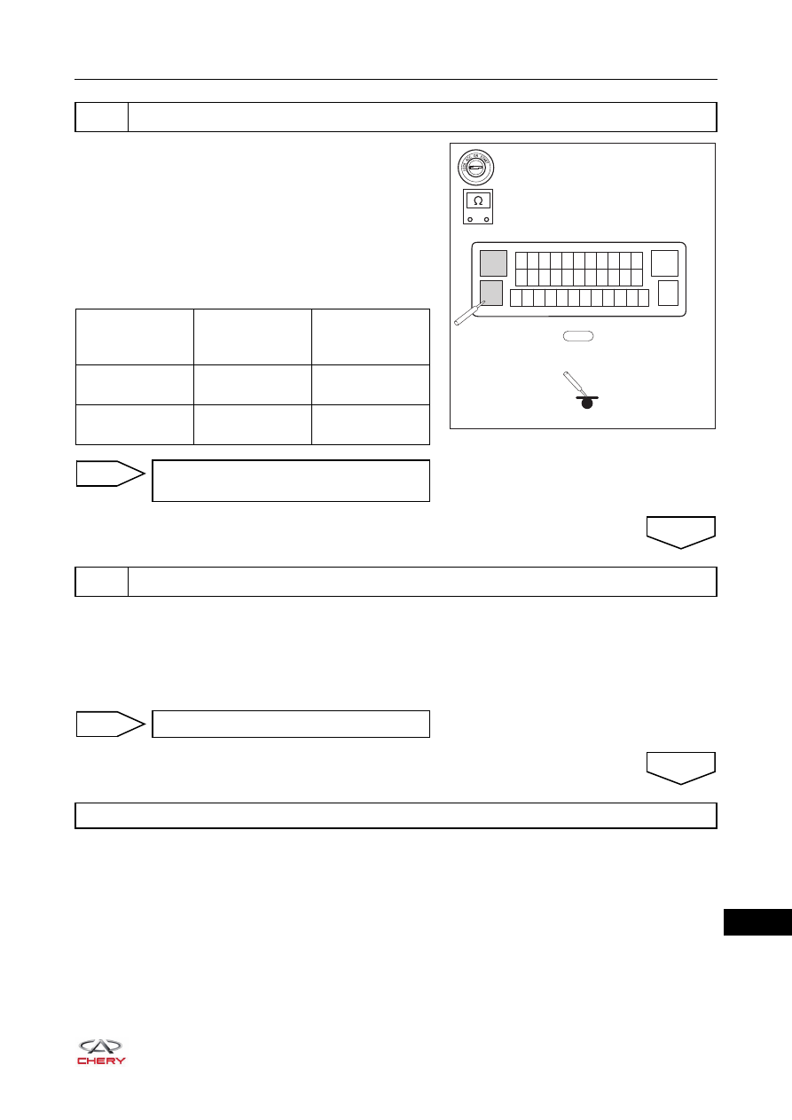
Check wire harness and connector (ABS control module assembly - body ground)
RT21250210
E-085
13
12 11 10 9 8 7 6 5 4 3 2
24 23 22 21 20 19 18 17 16 15 14
37 36 35 34 33 32 31 30 29 28 27 26
1
38
25
-
+
Multimeter
Connection
Terminal
Condition
Specified
Condition
E-085 (13) - Body
ground
Always
Continuity
E-085 (38) - Body
ground
Always
Continuity
Repair or replace ABS control module
assembly wire harness and connector
NG
6
Reconfirm DTCs
OK
System operates normally
NO
Replace ABS control module assembly
YES
25–
66
25
DTC
C1001-04 ECU
DTC
C1009-00 ECU Hardware Related
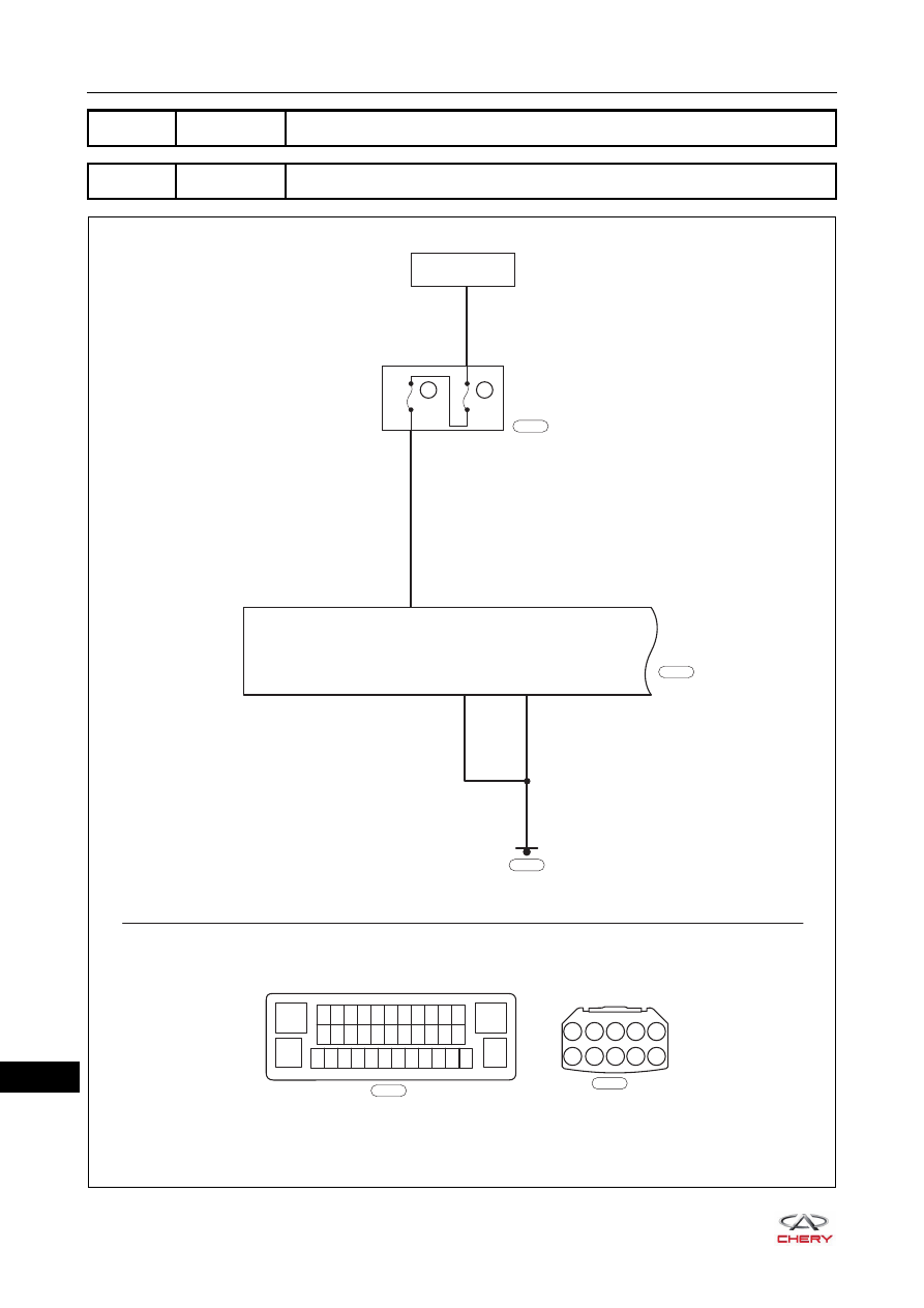
ET21250110
ABS
CONTROL
MODULE
IGNITION SWITCH
ON OR START
A10
28
EF34
20A
EF36
10A
ENGINE
COMPARTMENT
FUSE AND
RELAY BOX
RL
13
12 11 10 9 8 7 6 5 4 3 2
24 23 22 21 20 19 18 17 16 15 14
37 36 35 34 33 32 31 30 29 28 27 26
1
38
25
Gr
E-076
A1
A2
A3
A4
A5
A6
A7
A8 A9 A10
E-076
B
E-085
E-085
38
13
Br
B
E-042
25–
67
25
Diagnosis Procedure
a. Turn ignition switch to LOCK.
b. Disconnect the negative battery cable.
c. Remove the ABS fuse EF-36 (10 A) from the engine compartment fuse and relay box.
d. Check if the fuse is blown.
a. Turn ignition switch to LOCK.
b. Disconnect the negative battery cable.
c. Disconnect the ABS control module assembly connector E-085.
d. Check if the wire harnesses are worn, pierced, pinched or partially broken.
e. Look for broken, bent, protruded or corroded terminals.
f. Check if related connector pins are in good condition.
DTC Code
DTC Definitions
DTC Detection
Conditions
Possible Cause
C1001-04
ECU
These DTCs occur
when any of the
following conditions is
met:
1. ABS control module
assembly power
supply is
malfunctioning.
2. ABS control module
assembly is
damaged.
Fuse malfunction
Wire harness or connector damaged
ABS control module assembly
malfunction
C1009-00
ECU Hardware
Related
CAUTION
When performing electrical equipment diagnosis and test, always refer to the circuit diagram for related
circuit and component information.
1
Check ABS fuse
Replace ABS fuse
NG
2
Check ABS control module assembly wire harness and connector
OK
Repair or replace ABS control module
assembly wire harness and connector
NG
OK
25–
68
25
a. Turn ignition switch to LOCK.
b. Disconnect the negative battery cable.
c. Disconnect the ABS control module assembly connector
E-085.
d. Connect the negative battery cable.
e. Turn ignition switch ON.
f. Using a digital multimeter, measure the supply voltage
between ABS control module assembly connector E-085
and body ground to check if the power supply circuit is
normal according to the table below.
Standard Voltage
a. Turn ignition switch to LOCK.
b. Disconnect the negative battery cable.
c. Disconnect the ABS control module assembly connector
E-085.
d. Using a digital multimeter, check for continuity between
ABS control module assembly connector E-085 and body
ground to check if the system ground circuit is normal
according to the table below.
Standard Condition
3
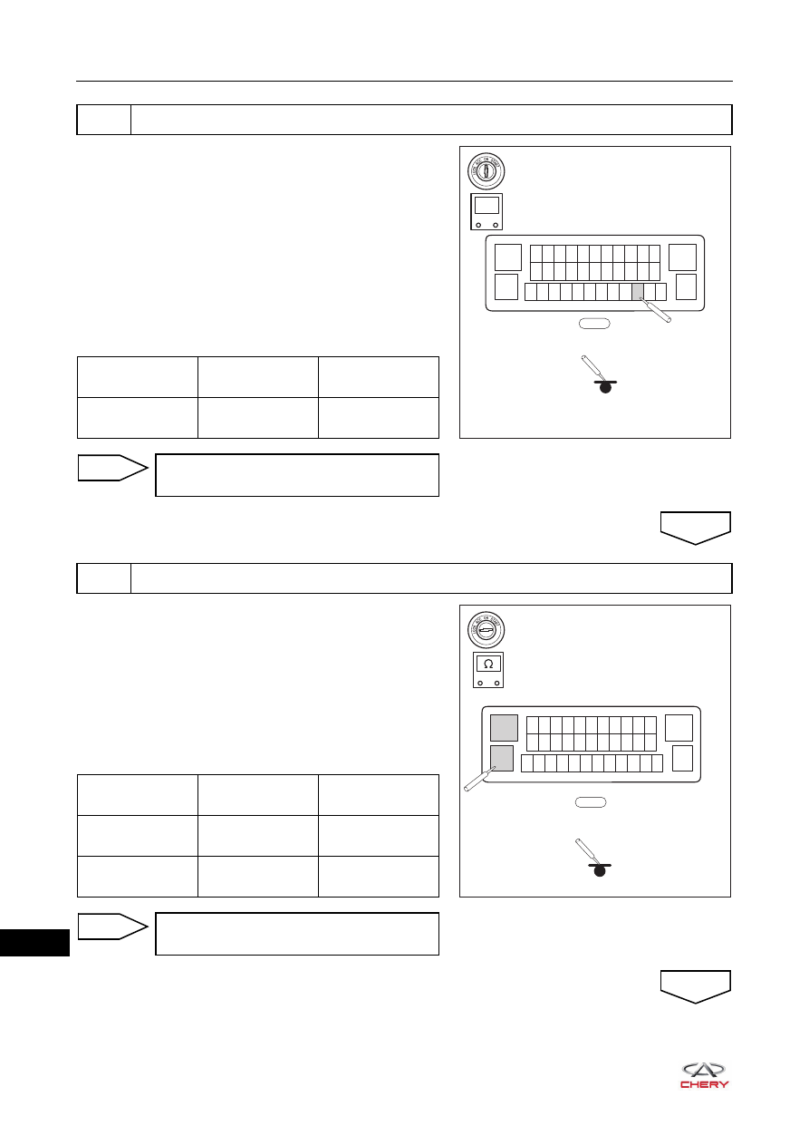
Check wire harness and connector (ABS control module assembly - battery)
RT21250470
E-085
13
12 11 10 9 8 7 6 5 4 3 2
24 23 22 21 20 19 18 17 16 15 14
37 36 35 34 33 32 31 30 29 28 27 26
1
38
25
-
+
V
Multimeter
Connection
Condition
Specified
Condition
E-085 (28) - Body
ground
Ignition switch ON
9 to 16 V
Repair or replace engine compartment
wire harness and connector
NG
4
Check wire harness and connector (ABS control module assembly - body ground)
OK
RT21250210
E-085
13
12 11 10 9 8 7 6 5 4 3 2
24 23 22 21 20 19 18 17 16 15 14
37 36 35 34 33 32 31 30 29 28 27 26
1
38
25
-
+
Multimeter
Connection
Condition
Specified
Condition
E-085 (13) - Body
ground
Always
Continuity
E-085 (38) - Body
ground
Always
Continuity
Repair or replace ABS control module
assembly wire harness and connector
NG
OK
Нет комментариевНе стесняйтесь поделиться с нами вашим ценным мнением.
Текст