Chery Tiggo 5 (T21). Service manual — part 509
47–
52
47
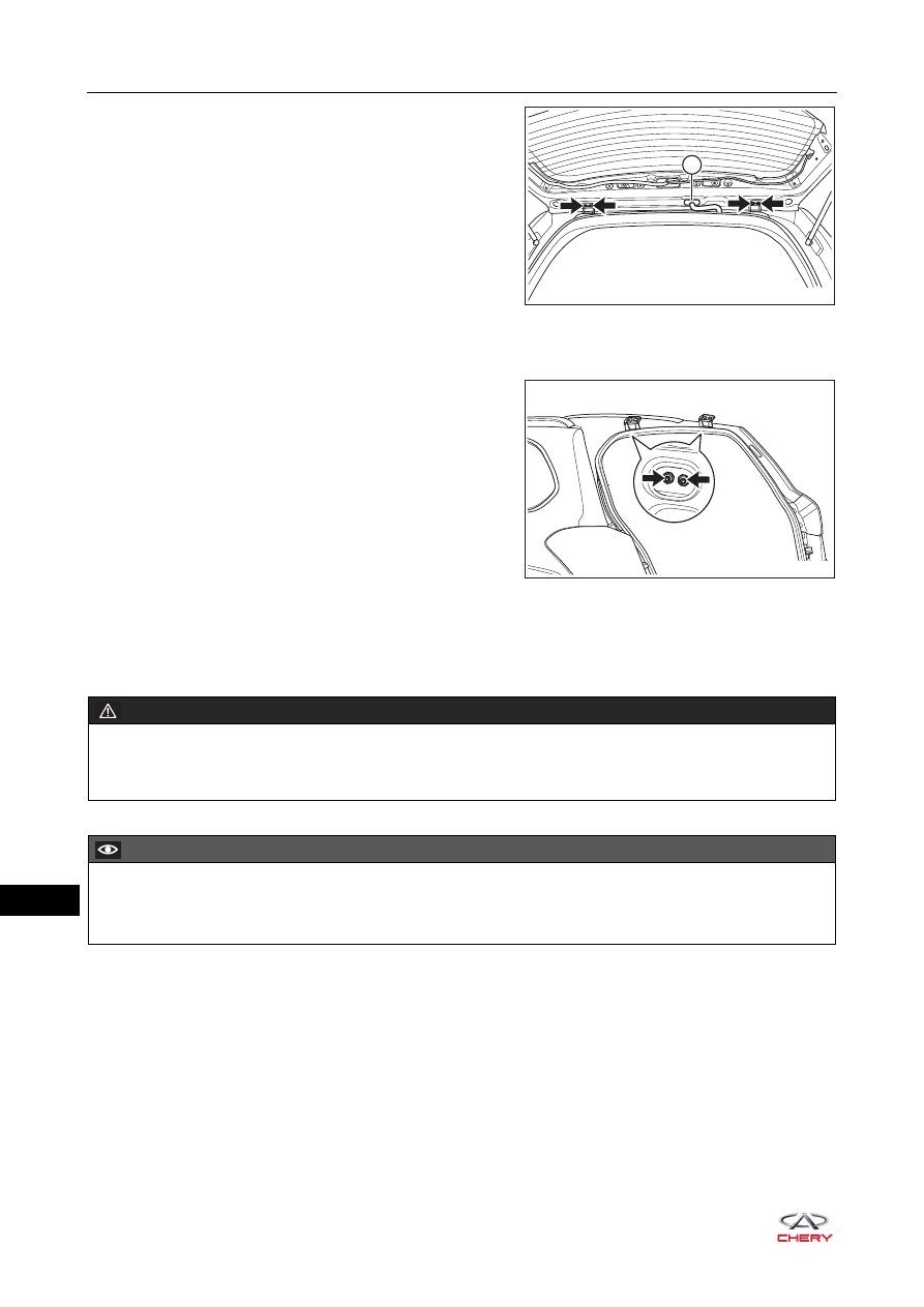
d. Using a screwdriver wrapped with protective tape, pry
up the back door dust boot (1).
e. Remove 4 fixing bolts (arrow) between back door
hinge assembly and back door.
(Tightening torque: 23 ± 2 N·m)
f. Remove the back door assembly.
19.Remove the back door hinge assembly.
a. Remove 4 fixing nuts (arrow) from the back door
hinge assembly.
(Tightening torque: 23 ± 2 N·m)
b. Remove the back door hinge assembly.
Installation
Installation is in the reverse order of removal.
1
RT21470800
RT21470810
WARNING
When installing back door assembly, an assistant is needed to hold back door. Prevent back door from
dropping or sudden closing to cause accidents during operation.
CAUTION
Be sure to wear safety equipment to prevent accidents when installing back door assembly.
Try to prevent body paint surface from being scratched when installing back door assembly.
47–
53
47
Adjustment
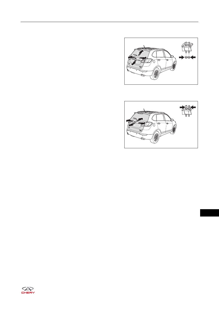
1. Adjust the back door assembly.
a. Loosen the fixing nuts on the back door assembly and
adjust the position of back door assembly in the
direction of arrow as shown in the illustration.
b. Tighten the fixing nuts on back door assembly to the specified torque after adjustment.
(Tightening torque: 23 ± 2 N·m)
c. Loosen the fixing bolts on back door assembly and
adjust the position of back door assembly in the
direction of arrow as shown in the illustration.
d. Tighten the fixing bolts on back door assembly to the specified torque after adjustment.
(Tightening torque: 23 ± 2 N·m)
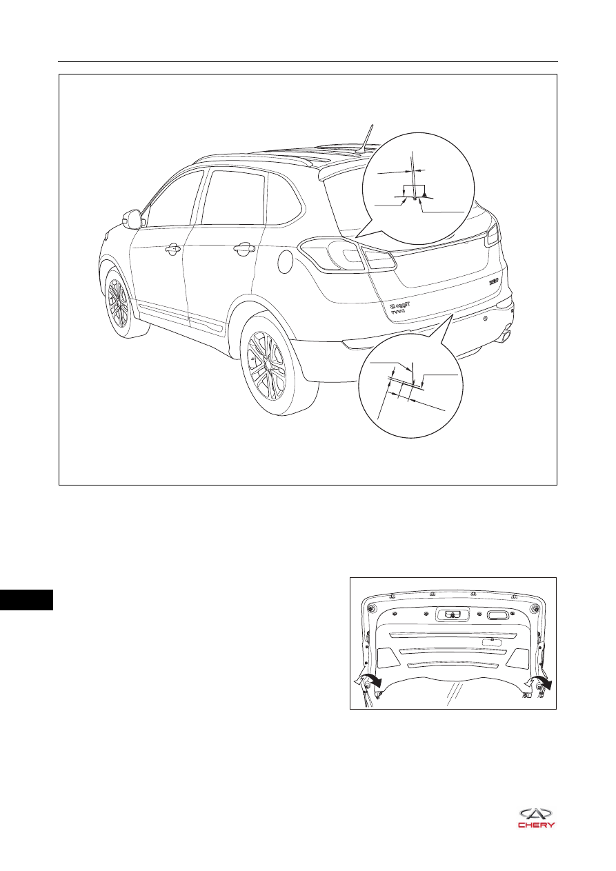
e. Standard ranges of clearance between installation positions of back door assembly and each part are
as follows:
Clearance between back door assembly and rear combination light assembly: 4.0 ± 1.5 mm.
Clearance between back door assembly and rear bumper assembly: 7.0 ± 2.0 mm.
RT21472000
RT21472001
47–
54
47
f. After adjustment, tighten fixing bolts between back door hinge assembly and back door assembly to the
specified torque.
(Tightening torque: 23 ± 2 N·m)
g. After adjustment, tighten fixing bolts between back door hinge and body to the specified torque.
(Tightening torque: 23 ± 2 N·m)
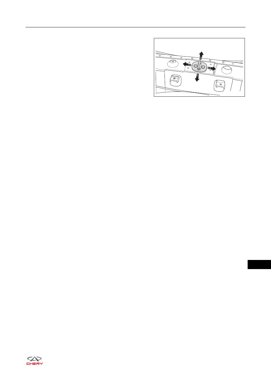
2. Adjust the height of back door with the back door adjustment block.
a. Lower or raise the back door by rotating the back door
adjustment blocks clockwise or counterclockwise.
4±1.5
0.7±1.2
7±2.0//2.0
Rear bumper
RT21470811
Back door
Rear combination
light
Back door
RT21470815
47–
55
47
3. Adjust the back door lock striker assembly.
a. Slightly loosen the fixing screws on back door lock
striker assembly and tap it with a plastic hammer in
the direction of arrow as shown in the illustration to
adjust the striker position.
b. Tighten the fixing screws on back door lock striker assembly to the specified torque after adjustment.
(Tightening torque: 10 ± 1 N·m)
Inspection
After back door assembly is adjusted, perform the following inspections:
1. Check back door for wear or deformation during installation, and repair as necessary.
2. Check if fixing bolts and fixing nuts are set in position. Tighten them to the specified torque as necessary.
3. Check if clearances and alignment between back door assembly and rear bumper are within the specified
range. Adjust if necessary.
RT21470817
Нет комментариевНе стесняйтесь поделиться с нами вашим ценным мнением.
Текст