Chery Tiggo 5 (T21). Service manual — part 220
18–
69
18
DTC Confirmation Procedure:
Confirm that battery voltage is between 11 and 14 V before performing the following procedures.
Turn ignition switch to LOCK.
Connect X-431 3G diagnostic tester (the latest software) to Data Link Connector (DLC), and make it
communicate with vehicle electronic module by the data network.
Turn ignition switch to ON.
Using X-431 3G diagnostic tester to record and clear the DTCs stored in the TCU.
Turn ignition switch to LOCK and wait for a few seconds.
Turn ignition switch to ON, and then select "Read Code".
If DTC is detected, the malfunction indicated by the DTC is current. Go to the diagnosis procedure - Step 1.
If DTC is not detected, the malfunction indicated by the DTC is intermittent. Please refer to Intermittent
DTC Troubleshooting.
Diagnosis Procedure
HINT:
After the fault is eliminated, verify DTC and symptom again.
a. Turn ignition switch to LOCK.
b. Disconnect the secondary shaft pressure sensor connector.
c. Check if the secondary shaft pressure sensor connector is dirty, oxidized, loose or damaged.
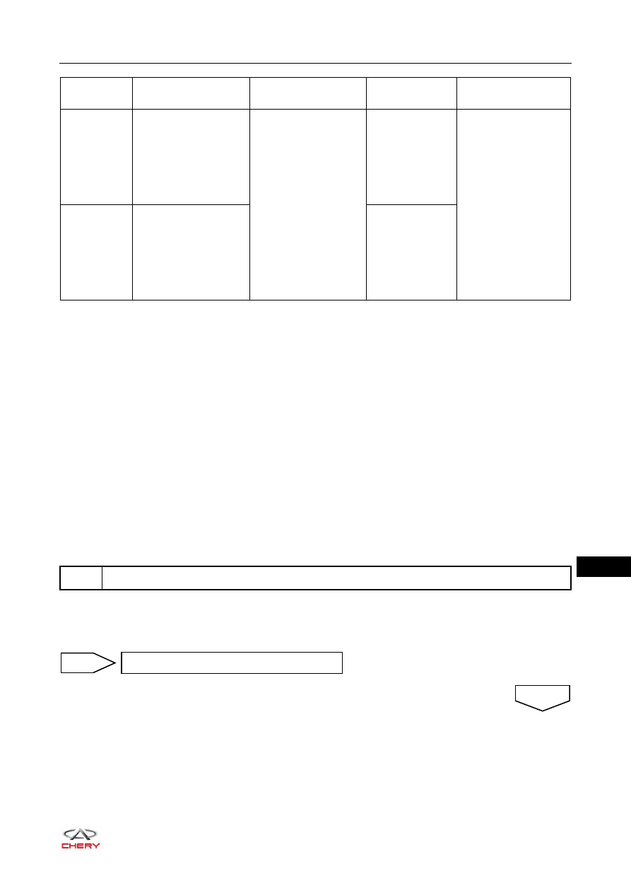
DTC Code
DTC Definition
DTC Detection
Condition
DTC Set
Condition
Possible Cause
P0847
Transmission Fluid
Pressure Sensor 'B'
Circuit Low
Start engine and wait
for at least 10 seconds
The transmission
fluid pressure
sensor 'B' oil
pressure is less
than the
allowable min
value
Transmission fluid
pressure sensor 'B'
failure
Signal circuit open
or short circuit
TCU signal circuit
failure
P0848
Transmission Fluid
Pressure Sensor 'B'
Circuit High
The transmission
fluid pressure
sensor 'B' oil
pressure is more
than the
allowable max
value
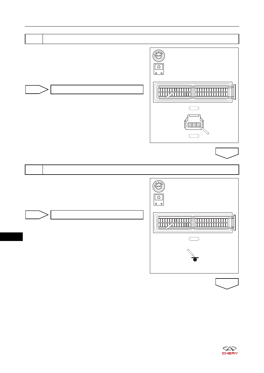
1
Check wire harness connector
Repair fault
NG
OK
18–
70
18
a. Turn ignition switch to LOCK and disconnect the negative
battery cable.
b. Disconnect the wire harness connectors E-030 and E-080.
c. Check for continuity between the terminals 12, 13, and
36 of wire harness connector E-030 and terminals 2, 3
and 1 of connector E-080.
a. Turn ignition switch to LOCK and disconnect the negative
battery cable.
b. Disconnect the wire harness connector E-030.
c. Check for continuity between the terminals 12, 13 and 36
of wire harness connector E-030 and ground.
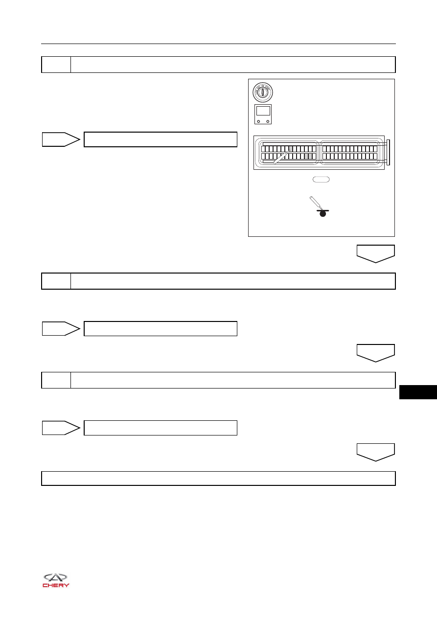
2
Check TCU wire harness
-
+
RT21181040
E-030
29 30 31 32 33 34 35 36 37 38 39 40 41 42
1 2 3 4 5 6 7 8 9 10 11 12 13 14
43 44 45 46 47 48 49 50 51 52 53 54 55 56
15 16 17 18 19 20 21 22 23 24 25 26 27 28
E-080
1
2
3
Repair failed circuit
NG
3
Check if TCU wire harness E-030 and ground is conductive
OK
-
+
RT21181050
E-030
29 30 31 32 33 34 35 36 37 38 39 40 41 42
1 2 3 4 5 6 7 8 9 10 11 12 13 14
43 44 45 46 47 48 49 50 51 52 53 54 55 56
15 16 17 18 19 20 21 22 23 24 25 26 27 28
Repair or replace failed circuit
NG
OK
18–
71
18
a. Turn ignition switch to LOCK and disconnect the negative
battery cable.
b. Disconnect the wire harness connector E-030.
c. Check if the terminals 12, 13, and 36 of wire harness
connector E-030 are short to power.
a. Correctly install a new secondary shaft pressure sensor.
b. Using the X-431 3G diagnostic tester, check whether the system is normal.
a. Using X-431 3G diagnostic tester, select Read Code.
b. Check if DTC P0847 or P0848 still exists.
4
Check if the TCU wire harness connector E-030 is short to power
RT21181060
E-030
29 30 31 32 33 34 35 36 37 38 39 40 41 42
1 2 3 4 5 6 7 8 9 10 11 12 13 14
43 44 45 46 47 48 49 50 51 52 53 54 55 56
15 16 17 18 19 20 21 22 23 24 25 26 27 28
-
+
V
Repair or replace failed circuit
NG
5
Check secondary shaft pressure sensor
OK
Diagnosis complete
NG
6
Check for DTC
OK
Replace TCU
NG
System is normal
OK
18–
72
18
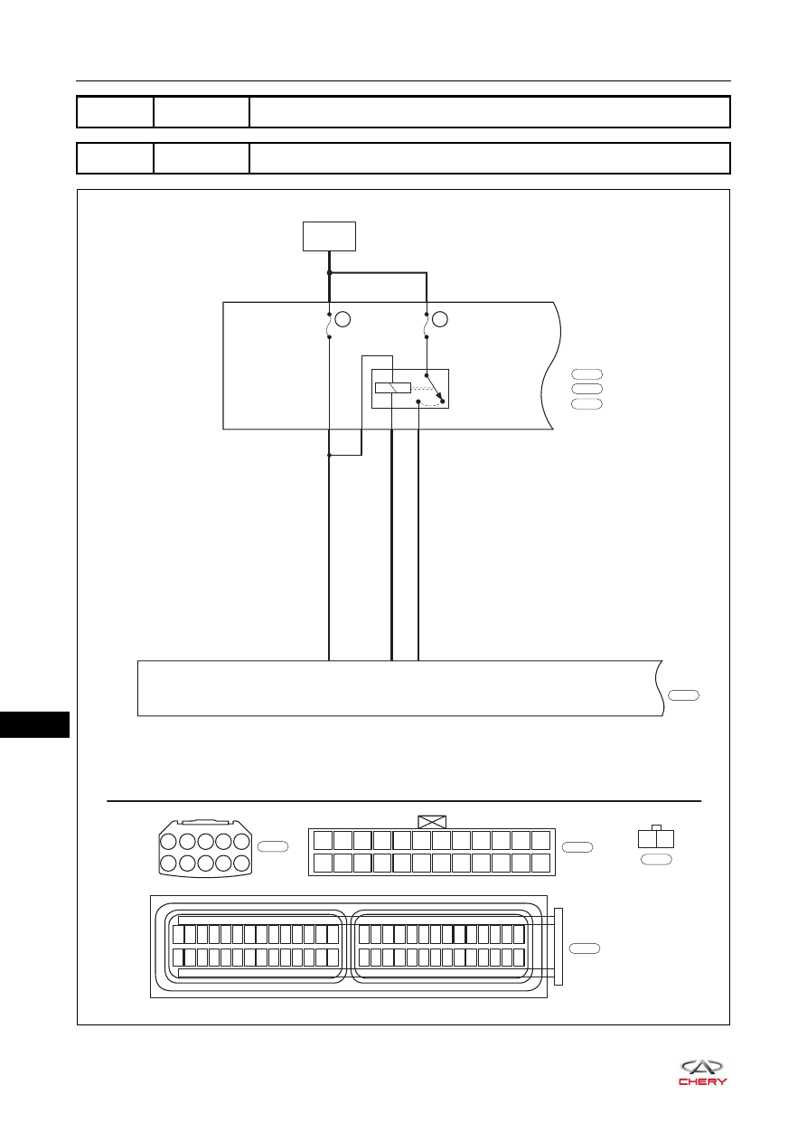
DTC
P0890
TCM Power Relay Sense Circuit Low
DTC
P0891
TCM Power Relay Sense Circuit High
ET21180140
BATTERY
TCU
TCU
RELAY
ERLY12
A2
J2
F16
85
30
86
87
31
56
3
RL
RL
R
EF19
10A
EF46
20A
A1
A2
A3
A4
A5
A6
A7
A8 A9 A10
J2
J1
F12
F24
F11
F23
F10
F22
F9
F21
F8
F20
F7
F19
F6
F18
F5
F17
F4
F16
F3
F15
F2
F14
F1
F13
29 30 31 32 33 34 35 36 37 38 39 40 41 42
1 2 3 4 5 6 7 8 9 10 11 12 13 14
43 44 45 46 47 48 49 50 51 52 53 54 55 56
15 16 17 18 19 20 21 22 23 24 25 26 27 28
ENGINE
COMPARTMENT
FUSE AND
RELAY BOX
Gr
E-076
W
E-069
B
E-066
B
E-030
E-069
E-076
E-030
E-066
F15
Нет комментариевНе стесняйтесь поделиться с нами вашим ценным мнением.
Текст