Chery Tiggo 5 (T21). Service manual — part 4
02–
15
02
CIRCUIT DIAGNOSIS INFORMATION
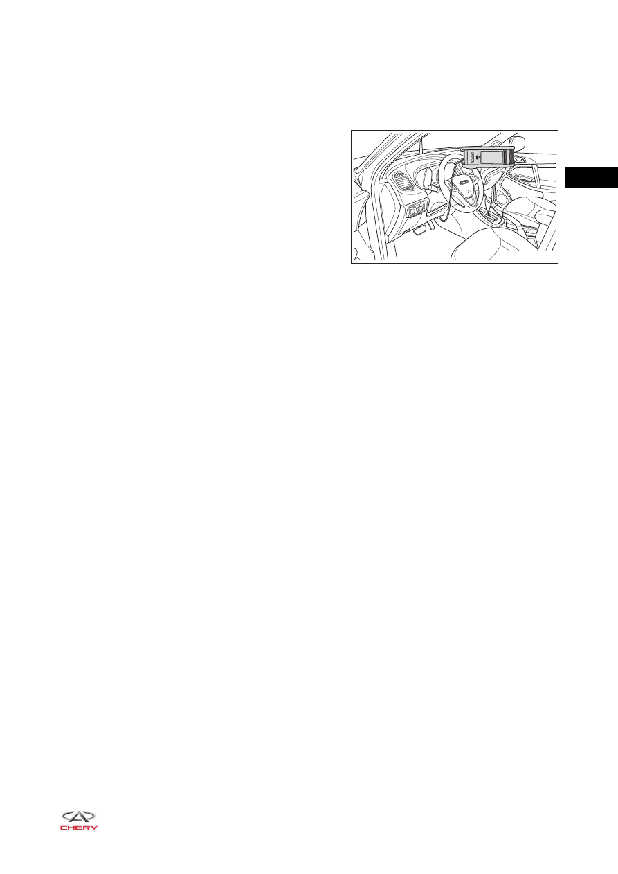
How to Use Tester
Connect tester cable to DLC, turn ignition switch ON and try
to use the tester. If communication malfunction appears on
the display, it indicates that the vehicle or tester is defective.
If communication is normal when the tester is connected
to another vehicle, inspect the DLC on the original
vehicle.
If communication is still not possible when the tester is
connected to another vehicle, the tester itself is probably
defective.
ECM Control System Troubleshooting
This model uses ECM control system. Most malfunction inspection procedures only involve in checking the
circuits of ECM control system one by one. An adequate understanding of the system and a basic knowledge
of electricity are enough to perform effective troubleshooting, accurate diagnosis and necessary repairs.
RT21020160
ཽ⪔⊳䖜
02–
16
02
Diagnosis and Troubleshooting
1. Diagnosis basis and troubleshooting methods
2. Detailed troubleshooting steps
Procedure Types
Details
Troubleshooting Methods
Diagnosis based on DTC
Diagnosis procedure is based on
stored DTC.
Use eliminating methods to
determine malfunctioning parts in
accordance with DTC detection
conditions.
Inspect relevant parts with tester
and eliminate possible
malfunctions one by one.
Diagnosis based on symptoms (no
DTCs stored)
Diagnosis procedure is based on
problem symptoms.
Use eliminating methods to
determine the malfunctioning parts
in accordance with symptoms.
Inspect relevant parts with tester
and eliminate possible
malfunctions one by one.
Step
Description
1
Obtain detailed information when electrical malfunction occurs.
2
Operate affected system, and perform a road test as necessary.
Confirm malfunction parameter.
If it is impossible to duplicate malfunction, refer to "Electrical Malfunction Simulation Test".
3
Collect proper diagnosis materials, which includes:
Circuit Diagram
System Schematic Diagram
Relevant Chapter in Service Manual
Service Bulletin
Perform diagnosis according to the mastered system operation knowledge and customer's
feedback.
4
Check if there is any bonding, loose connector or damaged wire harness in the system.
Determine related circuits and components, and diagnose according to the circuit diagram and
wire harness layout diagram.
5
Repair circuit and replace component as necessary.
6
Operate system in all modes. Confirm that system can operate normally in all conditions.
Confirm that you have not inadvertently created new malfunctions during your diagnosis or
repair steps.
02–
17
02
Circuit Simulation Test
The non-regular malfunctions and other malfunctions that cannot be detected through a road test can be
detected by circuit simulation test. The possible vehicle malfunction can be determined efficiently by
simulating condition/environment when the malfunction occurs.
Simulation test can be classified into the following 7 types:
Vehicle vibration test
Thermosensitive test
Freezing test
Leakage test
Load test
Cold/hot start test
Voltage drop test
HINT:
It is extremely important to listen carefully to customer's description about the malfunction for simulating the
conditions when the symptoms occur.
1. Vehicle vibration test
When the vehicle is running on an uneven road or the engine is vibrating (A/C is on and engine is idling),
malfunctions may occur. In this case, check the conditions related to vibration. Check the following areas
on vehicle:
a. Connector and wire harness
Determine the connectors and wire harnesses that
may affect the electrical system being inspected.
When monitoring whether the system has
malfunctions that are being simulated, vibrate or
wiggle each connector and wire harness slightly. This
test may show loose or poor electrical connections.
HINT:
When connector is exposed to humid environment, a layer of corrosive film may form on its terminals.
With the connector connected, this condition may not be found by visual check.If an intermittent
malfunction occurs, it may be caused by corrosion. It is recommended that the terminals of relevant
connectors in the system should be checked and cleaned after disconnecting the connectors.
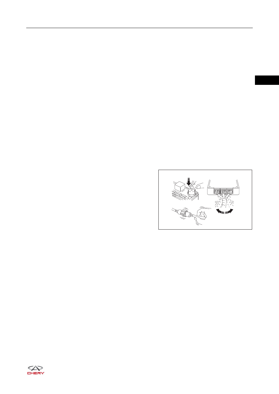
b. Sensors and relays.
Slightly vibrate the sensors and relays that you want to check in the system. The sensors or relays that
are loose or poorly installed may be found through this test.
RT21020170
Slightly Vibrate
Slightly Vibrate
Slightly Wiggle
02–
18
02
c. Engine compartment
There are many reasons for the electrical malfunction that occurred due to vehicle vibration, and it is
necessary to check the following conditions:
- Connectors are not installed correctly.
- Wire harness is not long enough, so it is extended when engine is vibrating or shaking.
- Wire harness hangs over the bracket or movable components.
- Ground wire is loose, dirty or corrosive.
- Wire harness is too close to the high temperature components.
To inspect the components under the engine hood, first confirm that the ground connection is in
perfect condition (refer to the grounding inspection described below). First confirm that the system is
correctly grounded. Then slightly vibrate the wire harness or components as previously instructed to
check if the connection is loose. Refer to the circuit diagram to check the continuity of wire harness.
d. Backside of instrument panel
Improper wire clamping will cause the wire harnesses to be entangled when installing accessories.
The vibration of vehicle will cause the wire harnesses near the bracket or mounting screw to wind
excessively.
When vehicle vibrates, unclamped or loose wire harness will be stuck in the seat components (such
as slide guide). When wire harness passes through the underside of mounting area, check if it is
damaged or stuck.
2. Thermosensitive test
In hot weather or after the vehicle is parked for a short time, the user may worry about the vehicle
condition. At this time, it is necessary to perform thermosensitive test.
Perform test by heating components with a heat gun or equivalent.
3. Freezing test
If malfunction disappears after warming up the vehicle in winter, it may be caused by freeze of some parts
in the wire harness/electrical system. Use the following two methods to check this condition:
Method 1: Put vehicle outdoors overnight. Make sure that the temperature is low enough to duplicate the
malfunction. Perform a quick and thorough diagnosis on the component that may be affected in the
morning.
Method 2: Put suspected part in refrigerating room and wait until it is frozen. Reinstall the component to
vehicle and check if malfunction reoccurs. If malfunction occurs, repair or replace the component.
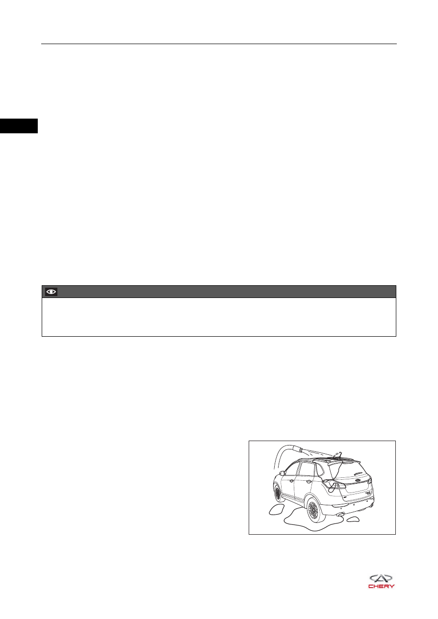
4. Leakage test
Malfunction may occur only during high humidity or in
rainy or snowy weather. In this case, malfunction may
occur due to water entering electrical parts. Leakage can
be checked by spraying water to vehicle (similar to car
wash).
CAUTION
DO NOT heat components to a temperature higher than 60°C (140°F).
Perform test by heating components with a heat gun or equivalent.
RT21020180
Нет комментариевНе стесняйтесь поделиться с нами вашим ценным мнением.
Текст