Chery Tiggo 5 (T21). Service manual — part 321
30–
16
30
a. Using X-431 3G diagnostic tester, read the EPS DTC.
b. Check if DTC C1901or C1902 still exists.
9
Check for DTCs
Replace EPS booster assembly
NG
The system is operating normally.
Reassemble the vehicle and perform a road test to confirm that the malfunction reported by the
customer has been repaired.
OK
30–
17
30
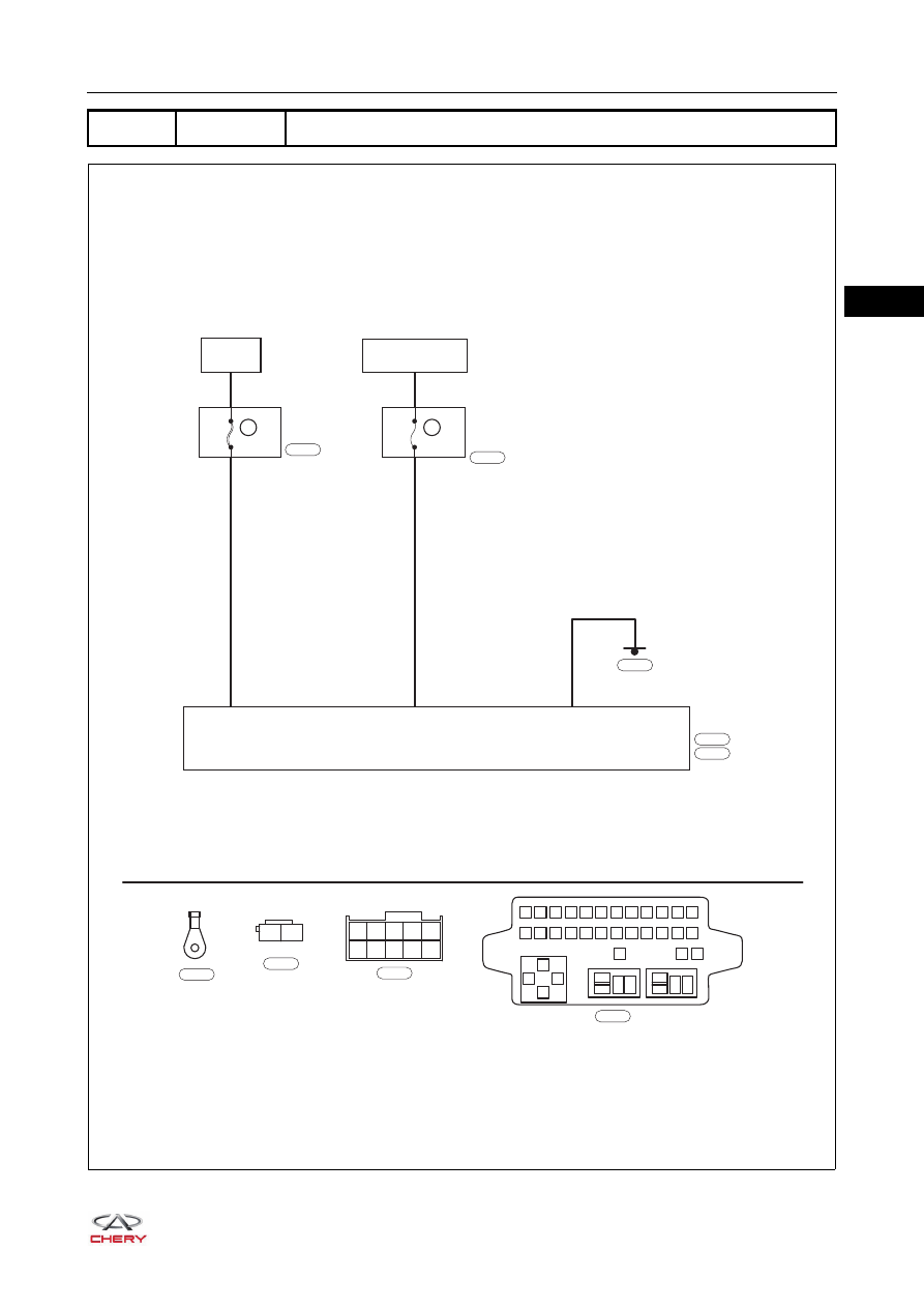
DTC
C1910
IGN Voltage Error
ET21300030
BATTERY
R
R
B
MF09
80A
7.5A
RF07
7
A1
B1
IGNITION SWITCH
ON OR START
INSTRUMENT
PANEL
FUSE AND
RELAY BOX
EPS
A2
B1
B2
B3
B4
B5
B6
B7
B8
B9
B10
1
2
3
4
5
6
7
8
9 10 11 12
13
85
85
87
87 30
87 30
30
86
86
85
86
14 15 16 17 18 19 20 21 22 23 24
25
27
26
B
I-007
B
I-057
I-007
L
E-077
A1
A2
E-077
E-081
E-064
EPS
POWER
E-064
I-057
30–
18
30
Diagnosis Procedure
a. Turn ignition switch to LOCK.
b. Check EPS ground point E-081.
a. Disconnect two EPS connectors.
b. Check connectors.
DTC
DTC Definition
Possible causes
C1910
IGN Voltage Error
Fuse
Wire harness or connector
EPS booster assembly
CAUTION
When performing the circuit diagnosis and test, always refer to the circuit diagram for the specific circuit
and the component information.
1
Check EPS ground point
Repair or replace ground wire harness or
ground point
NG
2
Check EPS connector
OK
Repair or replace EPS connector
NG
OK
30–
19
30
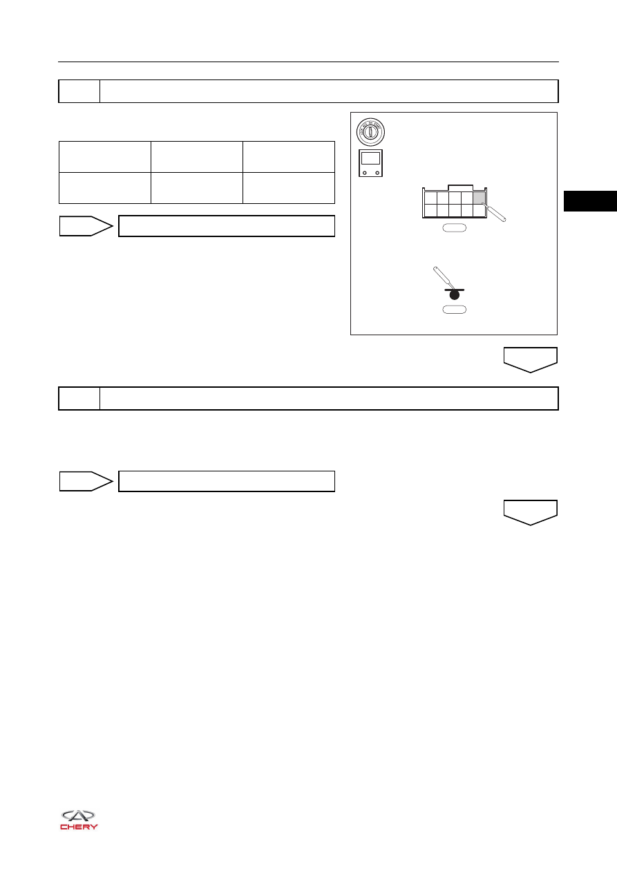
a. Measure voltage between terminal B1 of EPS connector
B I-057 and body ground.
a. Unplug EPS fuse RF07 (7.5 A) from instrument panel fuse and relay box.
b. Check resistance of fuse.
Standard resistance: less than 1 Ω
3
Check EPS ignition switch voltage
E-081
I-057
B1
B2
B3
B4
B5
B6
B7
B8
B9
B10
-
+
V
RT21305004
Multimeter
Connection
Condition
Specified
Condition
I-057 (B1) - Body
ground
Ignition switch ON
11 to 14 V
Go to step 8
OK
4
Check EPS fuse
NG
Replace fuse
NG
OK
Нет комментариевНе стесняйтесь поделиться с нами вашим ценным мнением.
Текст