Chery Tiggo 5 (T21). Service manual — part 270
25–
13
25
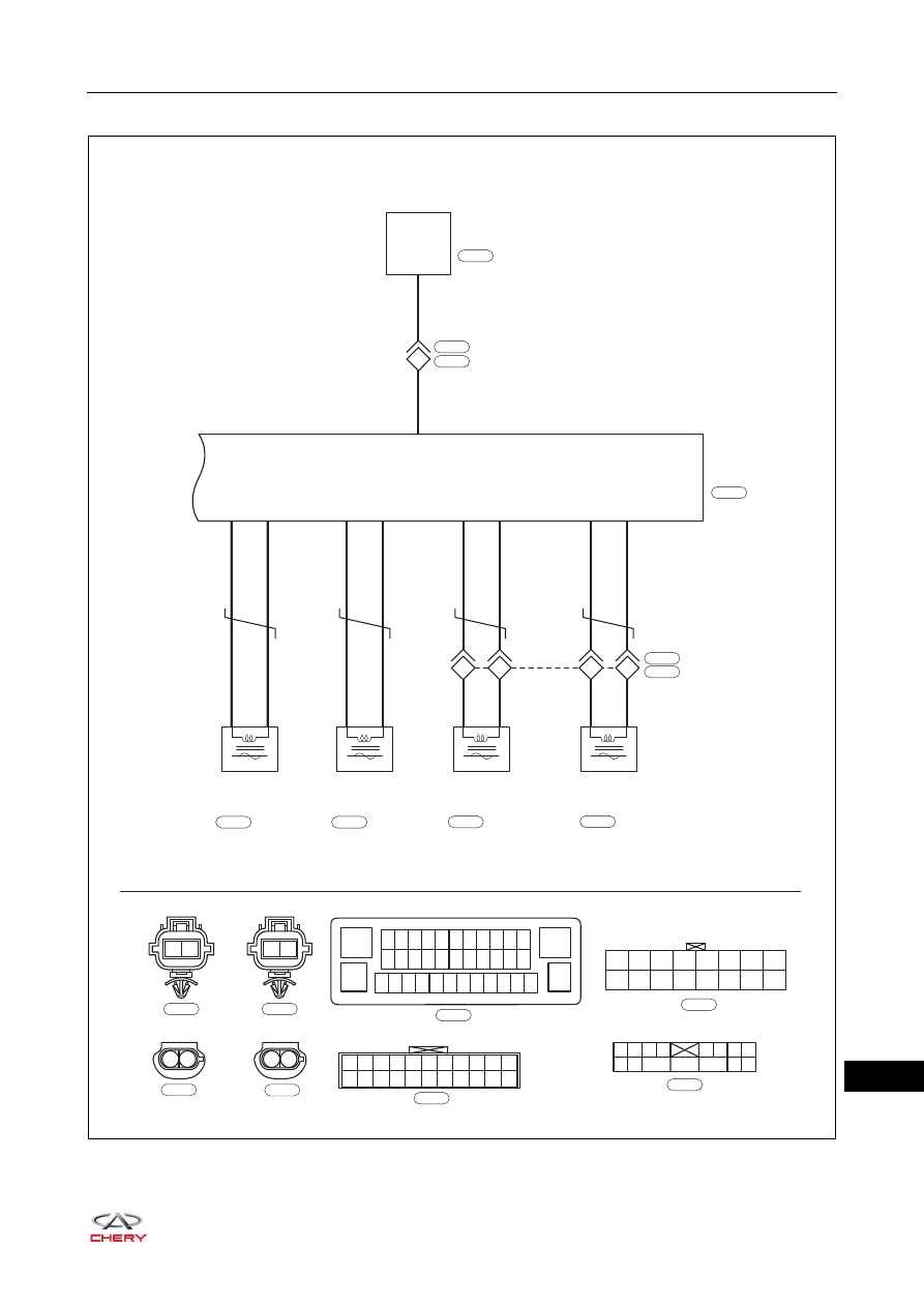
Brake Control System (Page 3 of 3)
ET21250030
17
29
31
18
16
4
19
8
2
1
2
1
1
2
1
2
FRONT LEFT
WHEEL SPEED
SENSOR
FRONT RIGHT
WHEEL SPEED
SENSOR
REAR LEFT
WHEEL SPEED
SENSOR
REAR RIGHT
WHEEL SPEED
SENSOR
R
Br
GY
WY
GR
GW
VB
V
GR
GW
VB
V
9
20
2
1
1
2
3
4
5
6
7
8
9
10
11
12
13
14
15
16
17
18
19
20
21
22
2
1
2
1
ABS
CONTROL
MODULE
13
12 11 10 9 8 7 6 5 4 3 2
24 23 22 21 20 19 18 17 16 15 14
37 36 35 34 33 32 31 30 29 28 27 26
1
38
25
B
E-085
E-085
W
E-029
B-054
E-029
B
B-009
B
B-029
B-009
B-029
B
E-036
B
E-060
1
2
1
2
E-036
E-060
LW
L
J107
2
3
E-027
I-034
PSE
CONNECTION
I-029
J101
J102
J103
J104
J105
J106
J107
J108
J109
J110
J111
J112
J113
J114
J115
J116
Gr
I-029
1
2
9
10
11
12
13
14
15
3
4
5
6
7
8
W
I-034
25–
14
25
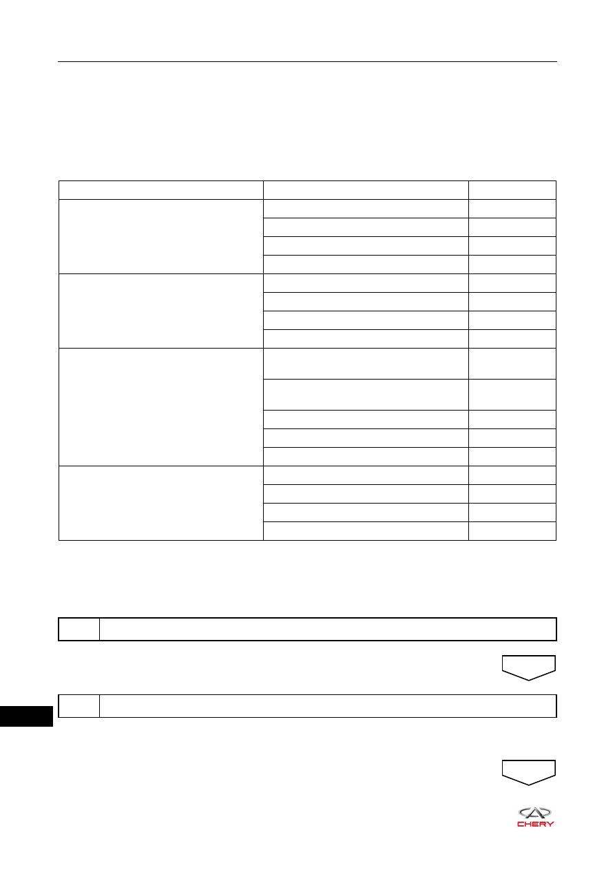
DIAGNOSIS & TESTING
Problem Symptoms Table
HINT:
Use the table below to help determine the cause of problem symptoms. Check each suspected area in
sequence. Repair or replace the faulty components, or adjust as necessary.
Diagnosis Procedure
HINT:
Use the following procedures to troubleshoot the Anti-lock Brake System (ABS).
Standard voltage: 11 to 14 V
If voltage is below 11 V, recharge or replace the battery before proceeding to next step.
Symptom
Suspected Area
See page
When turning ignition switch ON, ABS
warning light does not come on
ABS fuse
Wire harness or connector
-
ABS control module assembly
Instrument cluster
ABS warning light remains on
ABS fuse
Wire harness or connector
-
ABS control module assembly
Instrument cluster
ABS operation is abnormal
Wheel speed sensor (damaged, improper
installed, foreign matter attached)
Hub ring gear (damaged, improper
installed, foreign matter attached)
-
Brake line (blocked or leaked)
-
Wire harness or connector
-
ABS control module assembly
Communication with diagnostic tester
cannot be performed
ABS fuse
Wire harness or connector
-
X-431 3G diagnostic tester
-
ABS control module assembly
1
Vehicle brought to workshop
2
Check battery voltage
NEXT
NEXT
25–
15
25
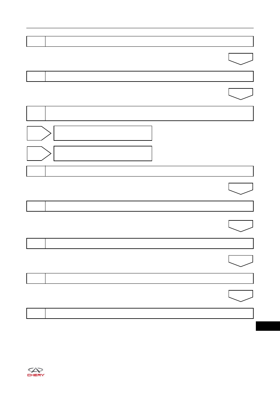
3
Customer problem analysis
4
Check and clear DTCs
5
Confirm and duplicate malfunction: accelerate vehicle to 15 km/h or more, simulate
malfunction conditions and read DTCs again
NEXT
NEXT
For current DTC, go to step 7
For history DTC, go to step 8
DTC
occurs
No
DTC
6
Problem repair (no DTC), then go to step 9
7
Troubleshoot according to Diagnostic Trouble Code (DTC) chart, then go to step 9
8
Troubleshoot according to Problem Symptoms Table, then go to step 9
9
Conduct test and confirm malfunction has repaired
10
End
NEXT
NEXT
NEXT
NEXT
25–
16
25
Problem Repair (No DTC)
If there is a problem in brake system, but no DTC is stored in ABS control module assembly, this problem is
called a problem without DTC. A problem without DTC is caused by basic brake system malfunction. For
example:
1. Brake fluid leakage (it may result in weak braking, brake pedal overtravel, or even ineffective braking).
2. Using inferior brake fluid (it can result in corrosion of brake line and ABS hydraulic regulating module
internal elements, or even ineffective braking).
3. Air in brake line (it may result in weak braking, or even ineffective braking).
4. Brake line blockage (it may result in hard braking, or even ineffective braking).
5. Excessive wear of brake disc (it may result in weak braking, brake pedal overtravel).
6. Brake booster malfunction (it may result in weak or hard braking, brake pedal overtravel, or even
ineffective braking).
7. Wrong brake line connection (it may result in braking performance decreasing, drift, long braking distance
etc.).
HINT:
ABS interrupted due to no power supply or power supply abnormality will cause the ABS warning light
remains on without storing DTC.
Troubleshooting method: check corresponding component according to the malfunction, repair or replace
as necessary.
DTC Confirmation Procedure
Confirm that battery voltage is normal before performing the following procedures.
Turn ignition switch to LOCK.
Connect X-431 3G diagnostic tester (the latest software) to Data Link Connector (DLC).
Turn ignition switch ON.
Using X-431 3G diagnostic tester to record and clear the DTCs stored in the ABS control module
assembly.
Turn ignition switch to LOCK and wait for a few seconds.
Start engine, drive the vehicle at 20 km/h or more and perform road test with X-431 3G diagnostic tester
connected to Data Link Connector (DLC).
Using X-431 3G diagnostic tester to select "Read Code".
If DTC is detected, the malfunction indicated by the DTC is current. Go to the diagnosis procedure - Step 1.
If DTC is not detected, the malfunction indicated by the DTC is intermittent. Please refer to Intermittent
DTC Troubleshooting.
Нет комментариевНе стесняйтесь поделиться с нами вашим ценным мнением.
Текст