Chery Tiggo 5 (T21). Service manual — part 418
37–
11
37
When "Succeeded to add old key!" is displayed,
click "OK".
Key match is completed.
d. The vehicle security has 6 modes (w/ passive entry & passive start):
Locking mode
Enter lock mode when the following conditions are met:
- All doors, engine hood and back door are closed.
- All doors are locked by operating the lock button on PEPS controller.
- All doors are locked by operating the front door handle button (REK of PEPS in the detecting
range of this door handle antenna).
When vehicle is in lock mode, following features will occur:
- Turn signal lights blink once, anti-theft horn sounds once and anti-theft indicator on the front left
door protector blinks normally to indicate that vehicle is in lock state.
- In lock state, if no door is opened within 30 seconds after unlocking the doors by wireless key, the
doors will lock again automatically.
Locking failure mode
System will enter lock failure mode under the following conditions and will show the following
features:
- When any door is not closed fully, turn signal lights blink twice anti-theft and horn does not
sound.
- When engine hood is not closed fully, turn signal lights blink twice, doors are locked and horn
does not sound.
- When back door is not closed fully, turn signal lights blink twice, doors are locked and horn does
not sound.
Lock deactivation mode
In lock mode, the locking mode of entire vehicle will be deactivated if the following condition occurs:
- Press the unlock button on PEPS controller.
- Press the front door handle button (REK of PEPS in the detecting range of this door handle
antenna).
When vehicle is in lock deactivation mode (by PEPS controller and front door handle button (REK of
PEPS in the detecting range of this door handle antenna)), following conditions will occur:
- All doors are unlocked.
- Turn signal lights blink twice, anti-theft horn does not sound and anti-theft indicator stops
blinking.
- Within 30 s after the doors are unlocked by wireless key, when no further operation is performed
(opening a door, opening engine hood and back door), the vehicle will return to the lock state.
If the following conditions occur within 30 s after the doors are unlocked by wireless key, the vehicle
will not return to the locking state, also not lock automatically:
- PEPS switch is in a position other than OFF.
- Any door is opened.
- Engine hood is opened.
Key match
Succeeded to add old key!
OK
RT21379947

37–
12
37
- Back door is opened.
Alarm mode
When vehicle is in lock mode, the alarm will be triggered if the following occurs:
- Open any door, engine hood and back door manually.
- Turn ignition switch to ON.
When vehicle is in alarm mode, the following occurs:
- After the alarm is triggered, turn signal lights blink and anti-theft horn sounds for 25 seconds. The
condition will occur again after an interval of 5 seconds. This process will repeat for 3 times. At
the same time, the security indicator blinks quickly to indicate system is in a state of insecurity. If
all doors/engine hood are fully closed or ignition switch is turned off during the cycle, the turn
signal lights will complete the cycle and all doors will lock again automatically after an interval of
5 seconds. At this time, the vehicle anti-theft system will be reactivated.
Alarm deactivation mode
The following operations will deactivate the alarm mode:
- Press the unlock button on PEPS controller.
- Press the front door handle button (REK of PEPS in the detecting range of this door handle
antenna).
Back door open mode
In the lock mode, if the back door opener switch on PEPS controller is pressed for more than 1.5
seconds, the back door will be opened but the anti-theft horn will not alarm.
When PEPS controller can be recognized by back door antenna, pressing the back door opener
switch can open the back door without sounding an alarm.
Specifications
Torque Specifications
Description
Torque (N·m)
Tank Upper Crossmember Deflector Fixing Nut
10 ± 1
Engine Hood Lock Assembly Fixing Nut
10 ± 1
Front Door Lock Assembly Fixing Screw
5.8 ± 0.7
Front Door Key Cylinder Cover Fixing Screw
5 ± 1
Front Door Lock Striker Assembly Fixing Screw
10 ± 1
Rear Door Lock Assembly Fixing Screw
5.8 ± 0.7
Rear Door Lock Striker Assembly Fixing Screw
10 ± 1
Back Door Lock Assembly Fixing Bolt
10 ± 1
Back Door Lock Striker Assembly Fixing Screw
10 ± 1
Auxiliary Fascia Console Rear Cover Plate
Assembly Fixing Screw
1.5 ± 0.5
Front Door Outside Handle Fixing Screw
1.5
Wireless Key Upper Cover Fixing Screw
0.4 ± 0.1
37–
13
37
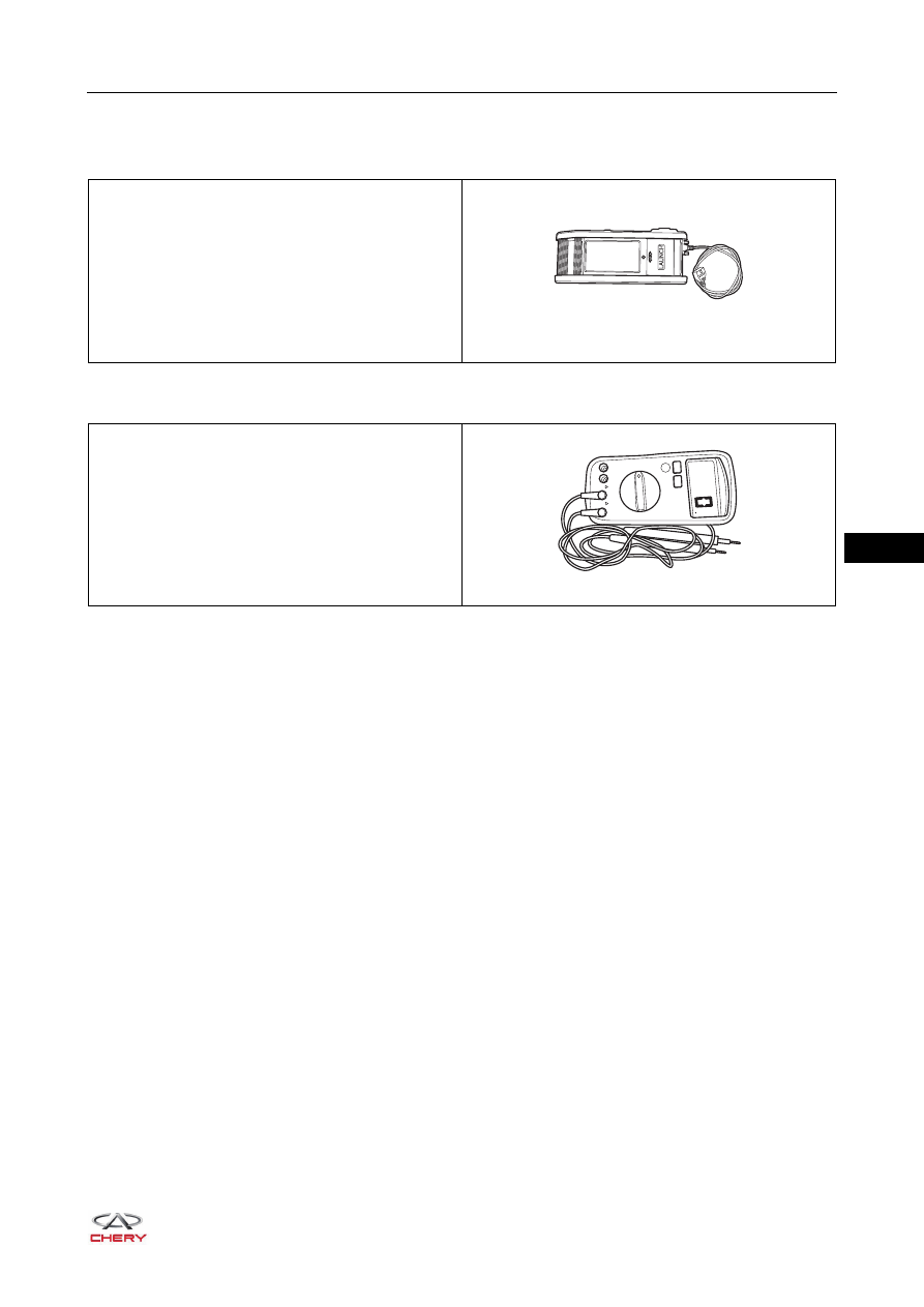
Tools
Special Tool
General Tool
X-431 3G Diagnostic Tester
RCH0000001
ཽ⪔⊳䖜
Digital Multimeter
RCH0000002
37–
14
37
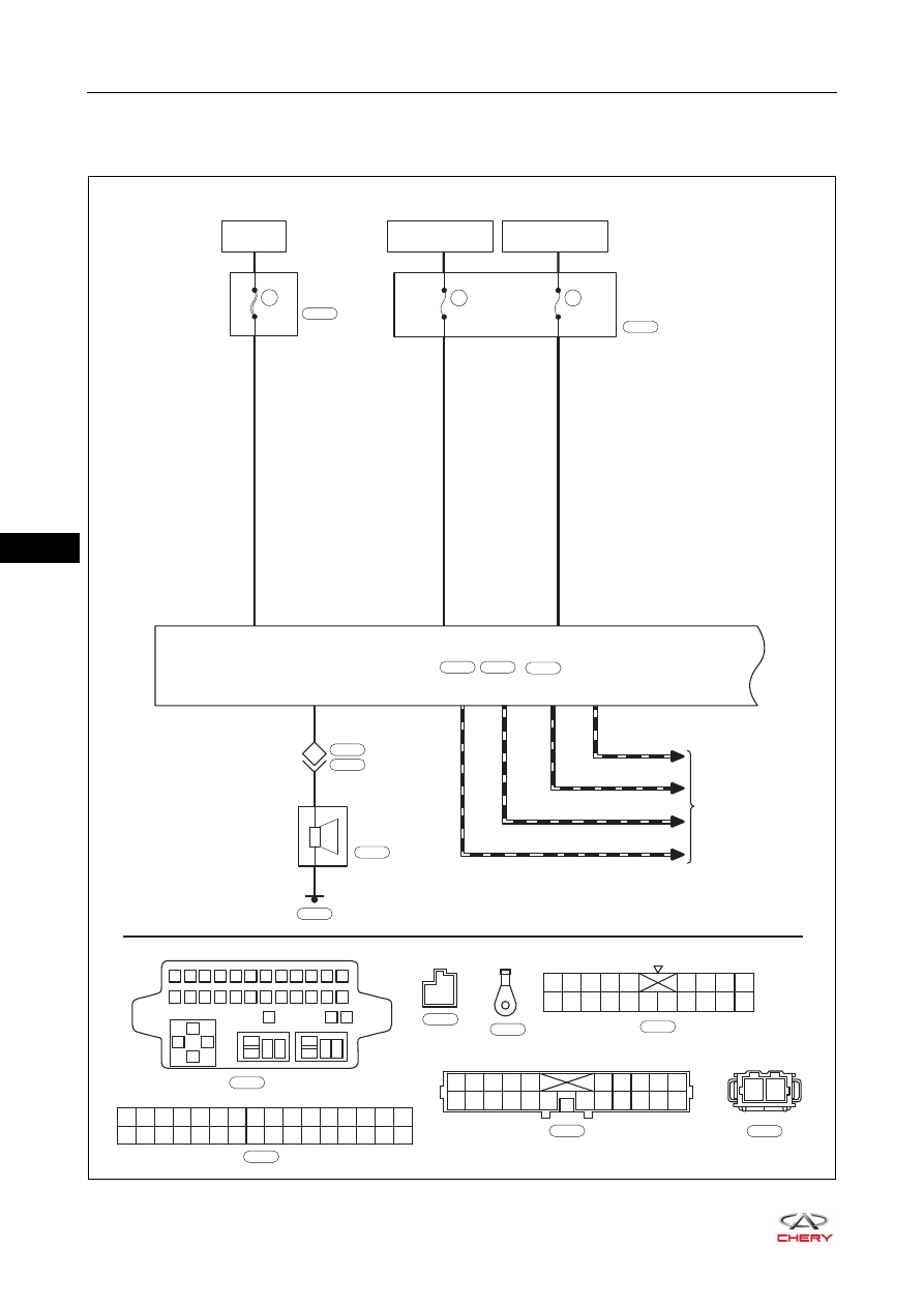
Circuit Diagram
Power Door Lock System (Page 1 of 3)
ET21370010
INSTRUMENT
PANEL FUSE
AND RELAY BOX A
IGNITION SWITCH
ON OR START
IGNITION SWITCH
ON OR ACC
R
RBr
7.5A
RF07
7.5A
RF13
TO CAN
SYSTEM
E1
A25
BATTERY
60A
MF03
CAN-H1
CAN-L2 CAN-H2
CAN-L1
OB
O
A30
A15
A14
A31
OB
O
BCM POWER
SUPPLY
7
3
RG
A9
13
1
2
3
4
5
6
7
8
9 10 11 12
13
85
85
87
87 30
87 30
30
86
86
85
86
14 15 16 17 18 19 20 21 22 23 24
25
27
26
A32
A31
A30
A29
A28
A16
A15
A14
A13
A12
A11
A10
A9
A8
A7
A6
A5
A4
A3
A2
A1
A27
A26
A25
A24
A23
A22
A21
A20
A19
A18
A17
BCM
3
E-061
E-061
W
E-072
E-072
E1
B
I-007
I-007
L
I-005
I-005
B
ANTI-THEFT
HORN
G
G
C4
2
1
6
E-053
E-032
B-043
B-048
E-070
C1
C10 C11 C12 C13 C14 C15 C16 C17 C18
C2 C3 C4 C5
C6 C7 C8 C9
C20
C19
W
B-043
2
1
1
2
3
4
5
11
12
13
14
15
6
7
8
9
10
22 21 20 19 18 17
16
B
E-053
W
B-048
Нет комментариевНе стесняйтесь поделиться с нами вашим ценным мнением.
Текст