Chery Tiggo 5 (T21). Service manual — part 71
06–
126
06
ET21065013
LL
BATTERY
ECM
MAIN
RELAY
10A
EF19
10A
EF17
10A
EF40
A2
F14
2-20
RL
A4
2-35
L
2-5
Br
A6
2-15
2-16
RR
R
86
87
85
30
ENGINE
COMPARTMENT
FUSE AND
RELAY BOX
IGNITION SWITCH
ON OR START
A1
A2
A3
A4
A5
A6
A7
A8 A9 A10
F12
F24
F11
F23
F10
F22
F9
F21
F8
F20
F7
F19
F6
F18
F5
F17
F4
F16
F3
F15
F2
F14
F1
F13
Gr
E-076
W
E-069
E-076
E-069
B
E-033
49 50 51
63
64
15
16
31
32
47
48
33 34 35
17 18 19
1
2
3
52 53 54 55 56 57 58 59 60 61 62
36 37 38 39 40 41 42 43 44 45 46
20 21 22 23 24 25 26 27 28 29 30
4
5
6
7
8
9 10 11 12 13 14
ECM-2
E-033
RL
C9
10A
EF27
1-30
2
1
11
E-007
E-038
C1
C2
C3 C4
C5
C6
C7
C8 C9 C10
L
E-023
1
2
3
4
5
6
7
8
9
10
11
12
13
14
15
16
17
18
19
20
21
22
23
24
25
26
31
35
39
40
41
42
32
33
36
37
38 34
27
28
29
30
B
E-007
37 38 39 40 41 42 43 44 45 46
47
48
25 26 27 28 29 30 31 32 33 34
35
36
13 14 15 16 17 18 19 20 21 22
23
24
1
2
3
4
5
6
7
8
9 10
11
12
B
E-035
ECM-1
E-035
E-023
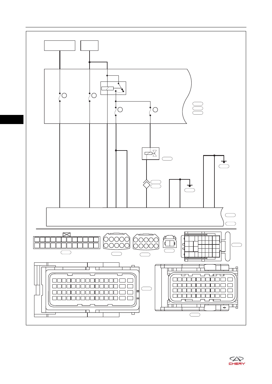
CANISTER
SOLENOID
VALVE
E-024
1
2
B
E-024
1-47
Br
Br
1-48
E-028
2-63
B
B
2-64
E-026
06–
127
06
DTC Confirmation Procedure
Confirm that battery voltage is over 12 V before performing the following procedures.
Turn ignition switch to LOCK.
Connect X-431 3G diagnostic tester (the latest software) to Data Link Connector (DLC).
Turn ignition switch to ON.
Use X-431 3G diagnostic tester to record and clear the DTCs stored in the ECM.
Start the engine and warm it up to normal operating temperature, and then select Read Code.
If the DTC is detected, the malfunction indicated by the DTC is current. Go to the diagnosis procedure - Step 1.
If DTC is not detected, the malfunction indicated by the DTC is intermittent (
).
Diagnosis Procedure
a. Turn ignition switch to LOCK.
b. Check ECM grounds E-026 and E-028 (
DTC Code
DTC Definition
DTC Detection
Condition
Possible Cause
P0444-00
Evaporative Emiss.
System Purge Control
Valve Circ. Open
Engine running
Canister solenoid valve
Wire harness or connector
ECM
P0458-00
Evaporative Emission
System Purge Control
Valve Circuit Low
P0459-00
Evaporative Emission
System Purge Control
Valve Circuit High
CAUTION
When performing circuit diagnosis and test, always refer to the circuit diagram for specific circuit and
component information.
1
Check ECM ground point
Repair or replace ground wire harness or
ground point
NG
OK
06–
128
06
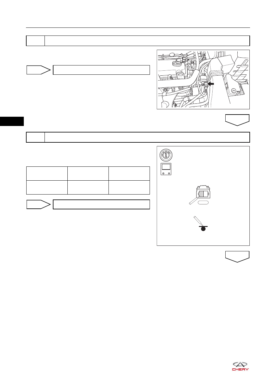
a. Disconnect canister solenoid valve connector E-024.
b. Check canister solenoid valve connector.
a. Turn ignition switch to ON.
b. Measure voltage between canister solenoid valve
connector terminal and body ground.
2
Check canister solenoid valve connector
RT21060240
Repair or replace connector
NG
3
Check canister solenoid valve power supply voltage
OK
E-024
1
2
-
+
V
RT21065047
Multimeter
Connection
Condition
Specified
Condition
E-024 (1) - Body
ground
Ignition switch ON
11 to 14 V
Go to step 5
OK
NG
06–
129
06
a. Turn ignition switch to LOCK.
b. Check fuse EF27 and main relay.
c. Disconnect engine compartment fuse and relay box
connector E-023.
d. Check wire harness between canister solenoid valve
connector terminals and engine compartment fuse and
relay box connector terminals.
Check for Open
Check for Short
4
Check canister solenoid valve power supply circuit
E-024
1
2
E-023
C1
C2
C3 C4
C5
C6
C7
C8 C9 C10
-
+
RT21065048
Multimeter
Connection
Condition
Specified
Condition
E-024 (1) -
E-023 (C9)
Always
Continuity
Multimeter
Connection
Condition
Specified
Condition
E-024 (1) or
E-023 (C9) -
Body ground
Always
No continuity
E-024 (1) or
E-023 (C9) -
Battery positive
Always
No continuity
Repair or replace wire harness or
connector (canister solenoid valve -
engine compartment fuse and relay box)
NG
OK
Нет комментариевНе стесняйтесь поделиться с нами вашим ценным мнением.
Текст