Chery Tiggo 5 (T21). Service manual — part 115
07–
46
07
Cylinder Head Cover
Removal
1. Turn off all the electrical equipment and ignition switch.
2. Disconnect the negative battery cable.
3. Remove the engine trim cover assembly (
).
4. Remove the cylinder head cover.
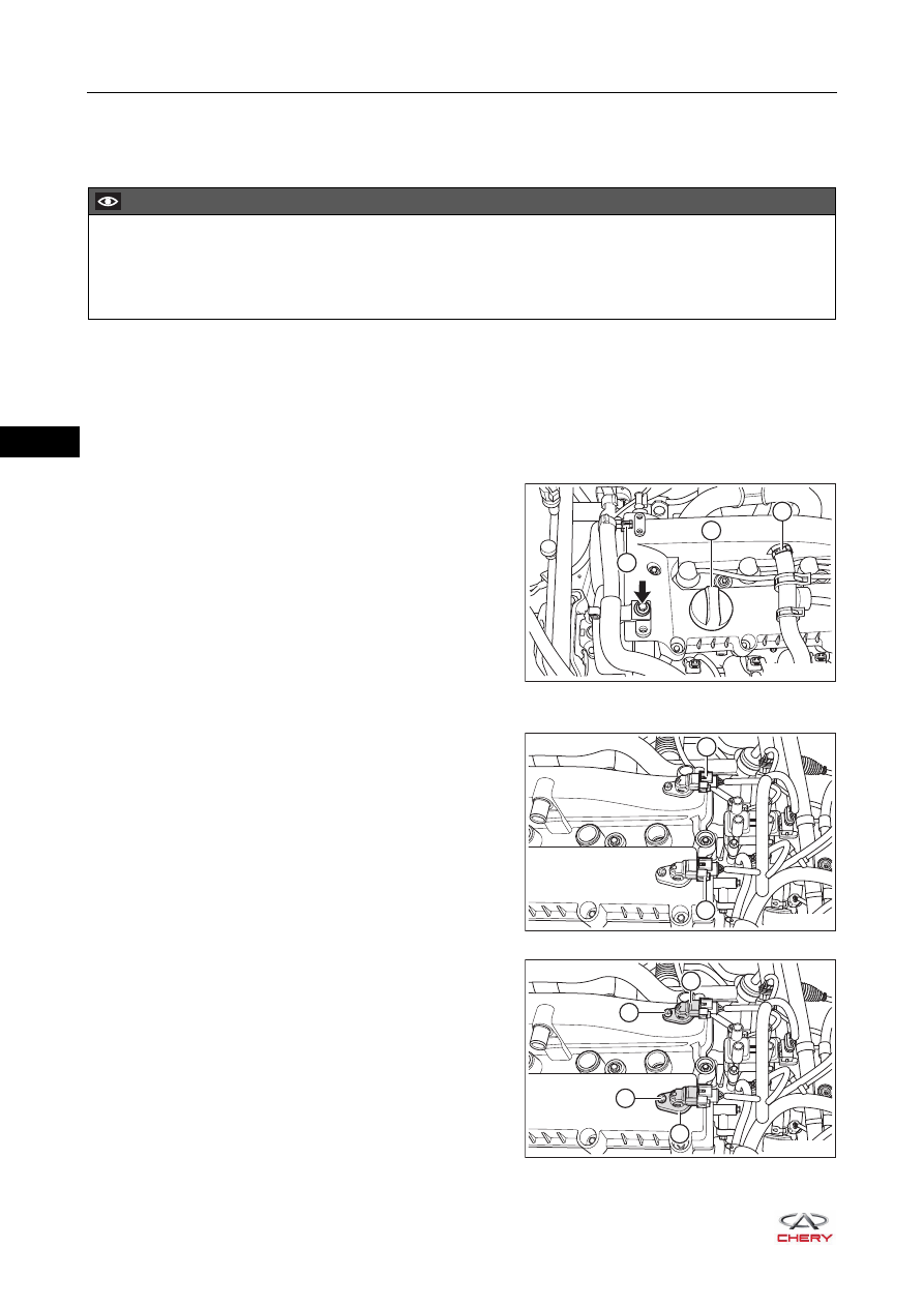
a. Remove the engine wire harness assembly fixing bolt (arrow).
(Tightening torque: 7 ± 1 N·m)
b. Remove the connecting clip (1) between engine wire
harness assembly and cylinder head cover.
c. Rotate the fuel tank cap (2) counterclockwise to
remove it.
d. Remove the clamp (3) and disconnect the connection
between crankcase ventilation hose and cylinder
head cover.
e. Remove the high-voltage cables (
f. Disconnect the intake camshaft position sensor
connector (1) and exhaust camshaft position sensor
connector (2).
g. Remove the fixing bolt (1) from intake camshaft
position sensor and remove the intake camshaft
position sensor (2) from cylinder head cover.
(Tightening torque: 8 ± 0.5 N·m)
h. Remove the fixing bolt (3) from exhaust camshaft
position sensor and remove the exhaust camshaft
position sensor (4) from cylinder head cover.
(Tightening torque: 8 ± 0.5 N·m)
CAUTION
Blow dirt and debris away from upper surface of cylinder head cover with compressed air.
Be sure to wear necessary safety equipment when repairing to prevent accidents.
Try to prevent body paint surface from being scratched during removal and installation.
2
3
1
RT21070310
1
2
RT21070320
RT21070330
3
1
4
2
07–
47
07
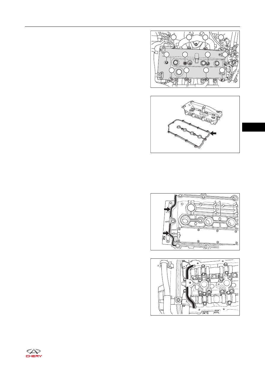
i. Remove 12 fixing bolts from cylinder head cover in the
order shown in the illustration.
(Tightening torque: 8 + 3 N·m)
j. Remove the cylinder head cover gasket (arrow) from
cylinder head cover.
5. Remove the trim cover rear right bracket and rear left bracket from cylinder head cover.
Installation
1. Remove the residue of seal gum on camshaft 1st bearing cap and cylinder head cover with a scraper.
2. Replace the cylinder head cover gasket.
3. Install the cylinder head cover gasket into the groove of
cylinder head cover.
HINT:
Before installing cylinder head cover gasket, apply seal
gum to the cylinder head cover groove in the areas as
shown in the illustration. Avoid gasket falling out from
groove during installation.
4. Apply seal gum to connecting part of camshaft 1st
bearing cap and cylinder head cover in the oval areas as
shown in the illustration.
4
8
5
11
12
10
9
3
7
6
2
1
RT21070340
RT21070350
RT21070360
RT21070370
07–
48
07
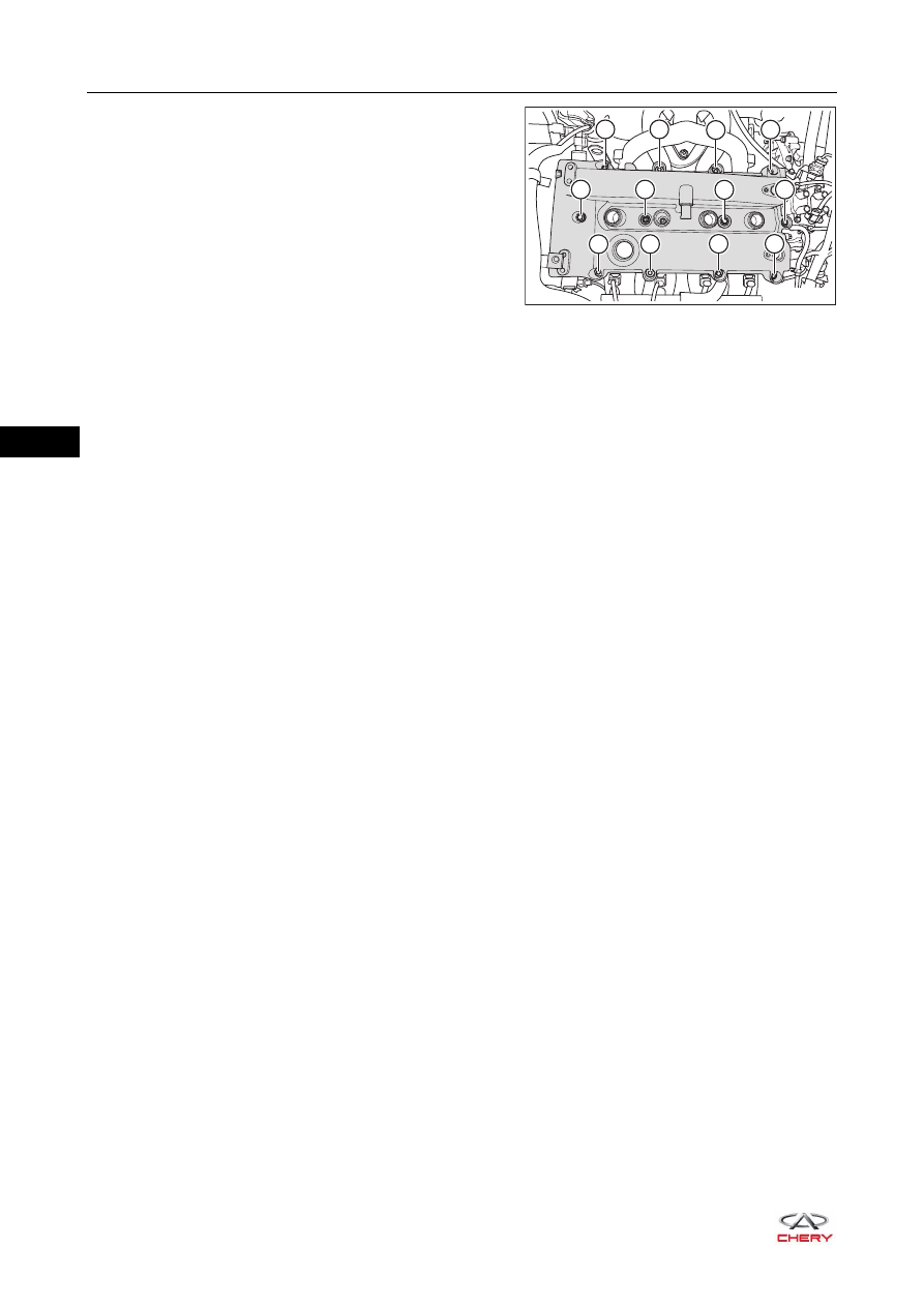
5. Install the cylinder head cover, and tighten the cylinder
head cover fixing bolts to the specified torque in
sequence shown in the illustration.
HINT:
First screw the bolts in order until they press against the
cylinder head and fit closely with cylinder head, then
tighten them again to the specified torque in order.
6. Other Installation procedures are in the reverse order of removal.
9
5
8
2
1
3
4
10
6
7
11
12
RT21070380
07–
49
07
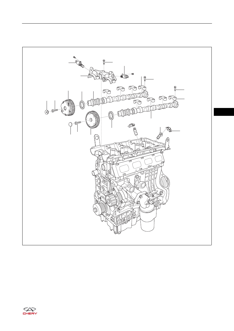
Camshaft
Description
RT21070390
×4
×4
×4
×4
×8
×8
×4
6
3
2
1
5
11
10
9
8
19
7
18
20
17
12
13
15
16
14
4
Нет комментариевНе стесняйтесь поделиться с нами вашим ценным мнением.
Текст